TROUBLE DIAGNOSIS
CAN FUNDAMENTAL
- Condition of Error Detection
- Symptom When Error Occurs in CAN Communication System
- CAN Diagnosis with CONSULT-III
- Self-Diagnosis
- CAN Diagnostic Support Monitor
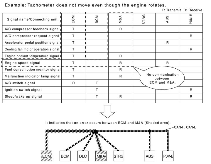
- How to Use CAN Communication Signal Chart
Condition of Error Detection
“U1000” or “U1001” is indicated on SELF-DIAG RESULTS on CONSULT-III if CAN communication signal is not transmitted or received between units for 2 seconds or more.
 CAN COMMUNICATION SYSTEM ERROR
- CAN communication line open (CAN-H, CAN-L, or both)
- CAN communication line short (ground, between CAN communication lines, other harnesses)
- Error of CAN communication control circuit of the unit connected to CAN communication line
WHEN “U1000” OR “U1001” IS INDICATED EVEN THOUGH CAN COMMUNICATION SYSTEM IS NORMAL- Removal/installation of parts: Error may be detected when removing and installing CAN communication unit and related parts while turning the ignition switch ON. (A DTC except for CAN communication may be detected.)
- Fuse blown out (removed): CAN communication of the unit may cease.
- Voltage drop: Error may be detected if voltage drops due to discharged battery when turning the ignition switch ON (Depending on the control unit which carries out CAN communication).
- Error may be detected if the power supply circuit of the control unit, which carries out CAN communication, malfunctions (Depending on the control unit which carries out CAN communication).
- Error may be detected if reprogramming is not completed normally.
NOTE:
CAN communication system is normal if “U1000” or “U1001” is indicated on SELF-DIAG RESULTS of CONSULT-III under the above conditions. Erase the memory of the self-diagnosis of each unit.Symptom When Error Occurs in CAN Communication System
In CAN communication system, multiple units mutually transmit and receive signals. Each unit cannot transmit and receive signals if any error occurs on CAN communication line. Under this condition, multiple control units related to the root cause malfunction or go into fail-safe mode.
ERROR EXAMPLENOTE:
- Each vehicle differs in symptom of each unit under fail-safe mode and CAN communication line wiring.
- Refer to Abbreviation List for the unit abbreviation.
 Example: TCM branch line open circuit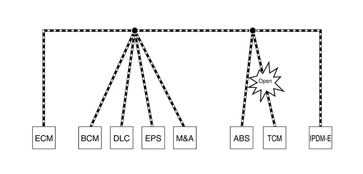
| Unit name | Symptom |
| ECM | Engine torque limiting is affected, and shift harshness increases. |
| BCM | Reverse warning chime does not sound. |
| EPS control unit | Normal operation. |
| Combination meter |
|
| ABS actuator and electric unit (control unit) | Normal operation. |
| TCM | No impact on operation. |
| IPDM E/R | Normal operation. |
Example: Data link connector branch line open circuit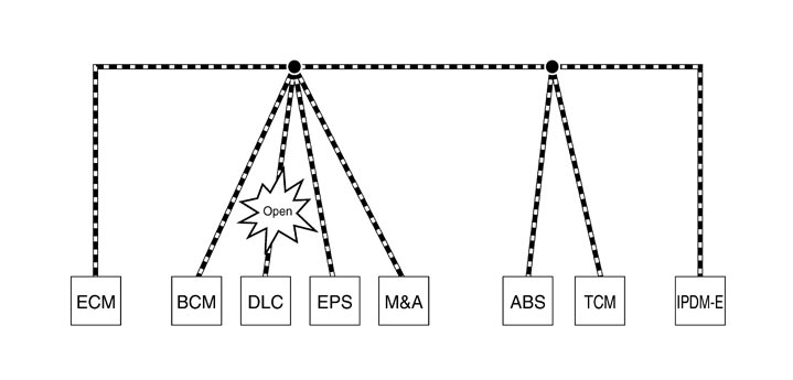
| Unit name | Symptom |
| ECM | Normal operation. |
| BCM | |
| EPS control unit | |
| Combination meter | |
| ABS actuator and electric unit (control unit) | |
| TCM | |
| IPDM E/R |
NOTE:
- When data link connector branch line is open, transmission and reception of CAN communication signals are not affected. Therefore, no symptoms occur. However, be sure to repair malfunctioning circuit.
- The model (all units on CAN communication system are Diag on CAN) cannot perform CAN diagnosis with CONSULT-III if the following error occurs. The error is judged by the symptom.
| Error | Difference of symptom |
| Data link connector branch line open circuit | Normal operation. |
| CAN‐H, CAN‐L harness short‐circuit | Most of the units which are connected to the CAN communication system enter fail-safe mode or are deactivated. |
Example: Main Line Between Data Link Connector and ABS Actuator and Electric Unit (Control Unit) Open Circuit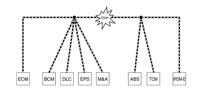
| Unit name | Symptom |
| ECM | Engine torque limiting is affected, and shift harshness increases. |
| BCM |
|
| EPS control unit | The steering effort increases. |
| Combination meter |
|
| ABS actuator and electric unit (control unit) | Normal operation. |
| TCM | No impact on operation. |
| IPDM E/R | When the ignition switch is ON,
|
Example: CAN-H, CAN-L Harness Short Circuit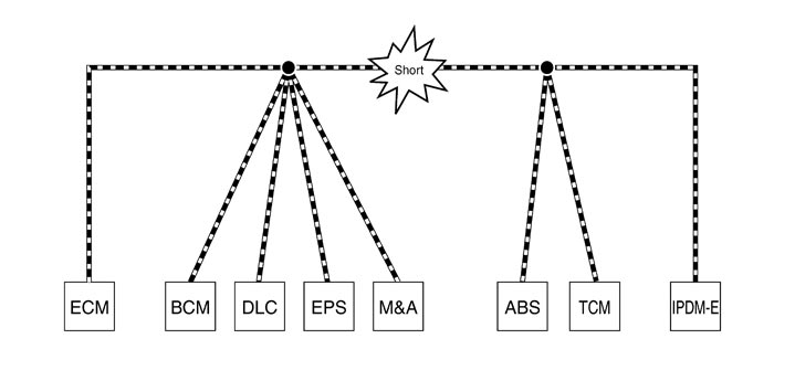
| Unit name | Symptom |
| ECM |
|
| BCM |
|
| EPS control unit | The steering effort increases. |
| Combination meter |
|
| ABS actuator and electric unit (control unit) | Normal operation. |
| TCM | No impact on operation. |
| IPDM E/R | When the ignition switch is ON,
|
CAN Diagnosis with CONSULT-III
CAN diagnosis on CONSULT-III extracts the root cause by receiving the following information.
- Response to the system call
- Control unit diagnosis information
- Self-diagnosis
- CAN diagnostic support monitor
Self-Diagnosis
|
DTC |
Self-diagnosis item (CONSULT-III indication) |
DTC detection condition |
Inspection/Action |
|
U0101 |
LOST COMM (TCM) |
When ECM is not transmitting or receiving CAN communication signal of OBD (emission-related diagnosis) from TCM for 2 seconds or more. |
Start the inspection. Refer to the applicable section of the indicated control unit. |
|
U0164 |
LOST COMM (HVAC) |
When ECM is not transmitting or receiving CAN communication signal of OBD (emission-related diagnosis) from HVAC for 2 seconds or more. |
|
|
U1000 |
CAN COMM CIRCUIT |
When a control unit (except for ECM) is not transmitting or receiving CAN communication signal for 2 seconds or more. |
|
|
U1001 |
CAN COMM CIRCUIT |
When ECM is not transmitting or receiving CAN communication signal other than OBD (emission-related diagnosis) for 2 seconds or more. |
|
|
U1002 |
SYSTEM COMM |
When a control unit is not transmitting or receiving CAN communication signal for 2 seconds or less. |
|
|
U1010 |
CONTROL UNIT(CAN) |
When an error is detected during the initial diagnosis for CAN controller of each control unit. |
Replace the control unit indicating “U1010” or “P0607”. |
|
P0607 |
ECM |
CAN Diagnostic Support Monitor
MONITOR ITEM (CONSULT-III)Example: CAN DIAG SUPPORT MNTR indication
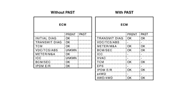 Without PAST
|
Item |
PRSNT |
Description |
|
Initial diagnosis |
OK |
Normal at present |
|
NG |
Control unit error (Except for some control units) |
|
|
Transmission diagnosis |
OK |
Normal at present |
|
UNKWN |
Unable to transmit signals for 2 seconds or more. |
|
|
Diagnosis not performed |
||
|
Control unit name (Reception diagnosis) |
OK |
Normal at present |
|
UNKWN |
Unable to receive signals for 2 seconds or more. |
|
|
Diagnosis not performed |
||
|
No control unit for receiving signals. (No applicable optional parts) |
With PAST|
Item |
PRSNT |
PAST |
Description |
|
Transmission diagnosis |
OK |
OK |
Normal at present and in the past |
|
1 – 39 |
Normal at present, but unable to transmit signals for 2 seconds or more in the past. (The number indicates the number of ignition switch cycles from OFF to ON.) |
||
|
UNKWN |
0 |
Unable to transmit signals for 2 seconds or more at present. |
|
|
Control unit name (Reception diagnosis) |
OK |
OK |
Normal at present and in the past |
|
1 – 39 |
Normal at present, but unable to receive signals for 2 seconds or more in the past. (The number indicates the number of ignition switch cycles from OFF to ON.) |
||
|
UNKWN |
0 |
Unable to receive signals for 2 seconds or more at present. |
|
|
– |
– |
Diagnosis not performed. |
|
|
No control unit for receiving signals. (No applicable optional parts) |
MONITOR ITEM (ON-BOARD DIAGNOSIS)NOTE:
For some models, CAN communication diagnosis result is received from the vehicle monitor.
Example: Vehicle Display
|
Item |
Result indicated |
Error counter |
Description |
|
CAN_COMM (Initial diagnosis) |
OK |
0 |
Normal at present |
|
NG |
1 – 50 |
Control unit error (The number indicates how many times diagnosis has been run.) |
|
|
CAN_CIRC_1 (Transmission diagnosis) |
OK |
0 |
Normal at present |
|
UNKWN |
1 – 50 |
Unable to transmit for 2 seconds or more at present. (The number indicates how many times diagnosis has been run.) |
|
|
CAN_CIRC_2 – 9 (Reception diagnosis of each unit) |
OK |
0 |
Normal at present |
|
UNKWN |
1 – 50 |
Unable to transmit for 2 seconds or more at present. (The number indicates how many times diagnosis has been run.) |
|
|
Diagnosis not performed. |
|||
|
No control unit for receiving signals. (No applicable optional parts) |
How to Use CAN Communication Signal Chart
The CAN communication signal chart lists the signals needed for trouble diagnosis. It is useful for detecting the root cause by finding a signal related to the symptom, and by checking transmission and reception unit.