MULTI AV SYSTEM
BOSE AUDIO WITH NAVIGATION
System Diagram
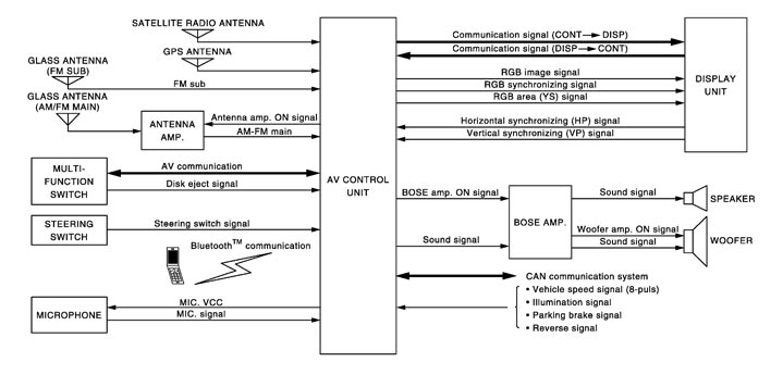
NOTE:
The name MULTIFUNCTION SWITCH indicates the integration of PRESET SWITCH, DISK EJECT SWITCH and MULTIFUNCTION SWITCH virtually.
System Description
Multi AV system means that the following systems are integrated.
| System name | System explanation |
| NAVIGATION SYSTEM | System Description |
| AUDIO SYSTEM | System Description |
| VEHICLE INFORMATION SYSTEM |
|
| HANDS‐FREE PHONE SYSTEM | Refer to the following “HANDS‐FREE PHONE SYSTEM”. |
| VOICE RECOGNITION SYSTEM | Refer to the following “VOICE RECOGNITION SYSTEM”. |
| TOUCH PANEL SYSTEM | Refer to the following “TOUCH PANEL SYSTEM”. |
| MULTI FUNCTION METER SYSTEM | Refer to the following “MULTIFUNCTION METER SYSTEM”. |
- AV control unit function by transmitting/receiving data one by one with each unit (slave unit) that configures them completely as a master unit by connecting between units that configure MULTI AV system with two AV communication lines (H, L).
- Two AV communication lines (H, L) adopt a twisted pair line that is resistant to noise.
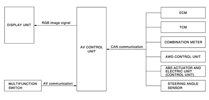
- The AV control unit is connected with CAN communication line and receives data signals from the ECM, combination meter, TCM, AWD control unit, A/C auto amp., ABS actuator and electric unit (control unit), steering angle sensor and low tire pressure warning control unit. Using the obtained information, it computes values for the display items relating to the fuel consumption information, multifunction meter, and tire pressure information and displays them.
- AV control unit is connected with display and serial communication, and it transmits the required signal of display and display control and receives the response signal from display. Also, it is connected with satellite radio by serial communication, and it transmits the operating signal and receives the display signal.
- The AV control unit, which has the vehicle setting function, transmits and receives data on vehicle setting condition via CAN communication with the BCM.
NOTE:
AV control unit can perform CONSULT-III self-operating function and on board self-diagnosis.- CONSULT-III self diagnosis: Refer to CONSULT-III Function.
- On board self diagnosis: Refer to Diagnosis Description.
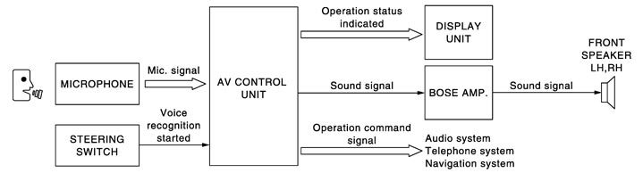
 HANDS‐FREE PHONE SYSTEM
- Hands‐free communication can be operated by connecting using BluetoothTM communication with cellular phone.
- Operation is performed by steering switch and multifunction switch, and operating condition is indicated on display.
- Guide sound that is heard during operation is input from AV control unit to BOSE amp., and is output from door speaker.

 When a call is originated
Spoken voice sound output from the microphone (Mic. Signal) is input to AV control unit. AV control unit outputs to cellular phone with BluetoothTM communication as a TEL voice signal. Voice sound is then heard at the other party.
When receiving a callVoice sound is input to own cellular phone from the other party. TEL voice signal is output to door speaker, and the signal is input to BOSE amp. via AV control unit by establishing BluetoothTM communication from cellular phone.
VOICE RECOGNITION SYSTEM- Each operation of multi AV system can be performed by inputting sound to microphone.
- Start of sound recognition system can be performed by steering switch.
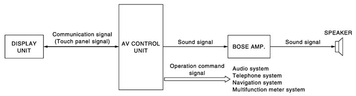
 TOUCH PANEL SYSTEM
Each operation of multi AV system can be performed by directly touching a display.
 MULTIFUNCTION METER SYSTEM
Multi function meter system can be performed with multi function switch.
- To inform the user of the most suitable usage of the high-performance vehicle, the mechanical information display function, driving assist display function, gear and fuel consumption display function, and driving history information display function are adopted.
- The necessary information is transmitted from each unit to the AV control unit via CAN communication to display on the multifunction meter.
- The multifunction meter has functions listed below.
Function Description Display Vehicle information mode Displays mechanical information to use the vehicle in good condition. CUSTOM VIEW 1
CUSTOM VIEW 2
CUSTOM VIEW 3
CUSTOM VIEW 4Driving assist display mode Displays major elements to improve the driving technique. ACCELERATION
BRAKING
STEERINGGear & fuel consumption display mode Displays proper gear selection, ECO level and fuel consumption to improve the fuel efficiency. GEAR POSITION
FUEL ECONOMYDriving history information display mode Displays the driving history (drive route and time). STOP WATCH
DRIVER'S NOTESNOTE:For further information about the procedure for handling and setting each function, refer to the Operation Manual.
Vehicle information modeTo continue to use the vehicle in good condition, it can display the mechanical information if necessary.
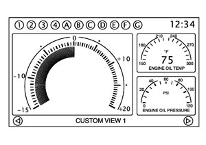
| Display | Display Item | Description | Signal route | Display form | Display range | Unit |
| CUSTOM VIEW 1 CUSTOM VIEW 2 CUSTOM VIEW 3 CUSTOM VIEW 4 | COOLANT TEMP | Engine coolant temperature | Coolant temperature sensor → ECM → Combination meter → AV control unit | Gauge | 50 - 130 | °C |
| Value | −40 - 200 | |||||
| Gauge | 120 - 270 | °F | ||||
| Value | −40 - 390 | |||||
| ENGINE OIL TEMP | Engine oil temperature | Fluid temperature sensor → ECM → Combination meter → AV control unit | Gauge | 70 - 150 | °C | |
| Value | −50 - 200 | |||||
| Gauge | 150 - 300 | °F | ||||
| Value | −50 - 390 | |||||
| ENGINE OIL PRESSURE | Engine oil pressure | Oil pressure sensor → Combination meter → AV control unit | Gauge | 0 - 8 | x100 kPa | |
| 0 - 120 | PSI | |||||
| TRANS OIL TEMP | Transmission oil temperature | Transmission oil sensor → TCM → Combination meter → AV control unit | Gauge | 40 - 160 | °C | |
| Value | −40 - 200 | |||||
| Gauge | 120 - 320 | °F | ||||
| Value | −40 - 390 | |||||
| TRANS OIL PRESSURE | Transmission oil pressure | Transmission oil pressure sensor → TCM → Combination meter → AV control unit | Gauge | Lo - Hi | — | |
| BOOST | Boost pressure | Boost sensor → ECM → Combination meter → AV control unit | Gauge | −1.0 - 1.5 | x100 kPa | |
| −15 - 20 | PSI | |||||
| SPEED | Vehicle speed (small display only) | Wheel sensor → ABS actuator and electric unit (control unit) → Combination meter → AV control unit | Value | 0 - 340 | km/h | |
| 0 - 215 | MPH | |||||
| FUEL/RANGE | Fuel level and possible driving distance | Combination meter → AV control unit | Gauge | E - F | — | |
| Value | 0 - 999 | km | ||||
| mile | ||||||
| FUEL FLOW | FUEL FLOW | ECM → AV control unit | Gauge | — | — | |
| CUSTOM VIEW 1 CUSTOM VIEW 2 CUSTOM VIEW 3 CUSTOM VIEW 4 | FUEL ECON. | Interval fuel consumption Small display: Fuel consumption in the last 20 seconds Large display: Interval fuel consumption history (20 minutes) | ECM → Combination meter → AV control unit | Value | 0 - 30 | l/100 km |
| Graph | 0 - 15 | |||||
| Value | 0 - 60 | MPG | ||||
| Graph | 0 - 30 | |||||
| TORQUE SPLIT | Front torque distribution (small display only) | AWD control unit → Combination meter → AV control unit | Gauge | RWD - 4WD | — | |
| ACCEL BRAKING G | Longitudinal G (Accelerator pedal/brake G) Small display: Real time display Large display: History display (for 20 seconds) | Yaw rate/side G/longitudinal G sensor → ABS actuator and electric unit (control unit) → AV control unit | Gauge | −1.5 - 1.5 | — | |
| Graph | Auto scale | — | ||||
| CORNERING G | Transverse G (Cornering G) Small display: Real time display Large display: History display (for 20 seconds) | Yaw rate/side G/longitudinal G sensor → ABS actuator and electric unit (control unit) → AV control unit | Gauge | −1.5 - 1.5 | — | |
| Graph | Auto scale | — | ||||
| TOTAL G | Synthetic G (Absolute G generated on the vehicle synthesized from longitudinal G and transverse G) Small display: Real time display Large display: History display (for 20 seconds) | Yaw rate/side G/longitudinal G sensor → ABS actuator and electric unit (control unit) → AV control unit | Gauge | 0 - 1.5 | — | |
| Graph | ||||||
| CLOCK | Clock (small display only) | GPS antenna → AV control unit | Value | 12/24 | Time | |
| ACCEL PEDAL | Accelerator pedal position (small display only) | ECM → AV control unit | Gauge | 0 - 100 | % | |
| BRAKE PEDAL | Braking pressure (small display only) | Pressure sensor -> ABS actuator and electric unit (control unit) -AV control unit | Gauge | 0 - 100 | % | |
| STEERING | Steering angle (small display only) | Steering sensor → AV control unit | Gauge | Auto scale | — |
Driving assist display modeDisplays major elements (accelerator, brake and steering operations) to improve the driving technique, and also displays the longitudinal/transverse G history.
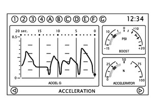
| Display | Display Item | Description | Signal route | Display form | Display range | Unit |
| ACCELERATION | ACCEL PEDAL | Accelerator pedal position | ECM → AV control unit | Gauge | 0 - 100 | % |
| BOOST | Boost pressure | Boost sensor → ECM → Combination meter → AV control unit | Gauge | −1.0 - 1.5 | x100 kPa | |
| −15 - 20 | PSI | |||||
| ACCEL G | History display of accelerator G (for 20 seconds) | Yaw rate/side G/longitudinal G sensor → ABS actuator and electric unit (control unit) → AV control unit | Graph | 0 - 1.5 | — | |
| BRAKING | BRAKE PEDAL | Braking pressure | Pressure sensor → ABS actuator and electric unit (control unit) → AV control unit | Gauge | 0 - 100 | % |
| SPEED | Vehicle speed | Wheel sensor → ABS actuator and electric unit (control unit) → AV control unit | Value | 0 - 340 | km/h | |
| 0 - 215 | MPH | |||||
| BRAKING G | History display of brake G (for 20 seconds) | Yaw rate/side G/longitudinal G sensor → ABS actuator and electric unit (control unit) → AV control unit | Graph | 0 - 1.5 | — | |
| STEERING | STEERING | Steering angle | Steering sensor → AV control unit | Gauge | Auto scale | — |
| SPEED | Vehicle speed | Wheel sensor → ABS actuator and electric unit (control unit) → AV control unit | Value | 0 - 340 | km/h | |
| 0 - 215 | MPH | |||||
| CORNERING G | History display of cornering G (for 20 seconds) | Yaw rate/side G/longitudinal G sensor → ABS actuator and electric unit (control unit) → AV control unit | Graph | −1.5 - 1.5 | — | |
| Gauge | Auto scale | — |
Gear & fuel consumption display modeDisplays proper gear selection to improve the fuel efficiency, and also displays fuel consumption and ECO driving level.
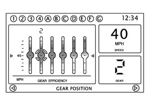
| Display | Display item | Description | Signal route | Display form | Display range | Unit |
| GEAR POSITION | GEAR | Selected gear position | Position sensor → TCM → Combination meter → AV control unit | Value/symbol | R, P, N, 1 - 6 | — |
| SPEED | Vehicle speed | Wheel sensor → ABS actuator and electric unit (control unit) → AV control unit | Value | 0 - 340 | km/h | |
| 0 - 215 | MPH | |||||
| GEAR EFFICIENCY | Displays ECO/power band per gear. | TCM → Combination meter → AV control unit | Special display | — | — | |
| FUEL ECONOMY | FUEL EFFICIENCY | Displays the current ECO level. | ECM → Combination meter → AV control unit | Gauge | 10 levels | — |
| FUEL ECON. | Interval fuel consumption | ECM → Combination meter → AV control unit | Value | 0 - 30 | l/100 km | |
| 0 - 60 | MPG | |||||
| FUEL EFFICIENCY | Displays the history of the ECO level. (for 20 seconds) | ECM/TCM/Combination meter → AV control unit | Graph | 10 levels | — |
Driving history information display modeDisplays the sub-functions (driving route history and required time history) indicating the driving history.
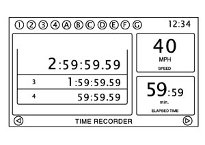
| Display | Description | Display form |
| STOP WATCH | Displays the measured TIME results. | Special display |
| DRIVER'S NOTES | Displays the driving history information | Special display |
Component Parts Location
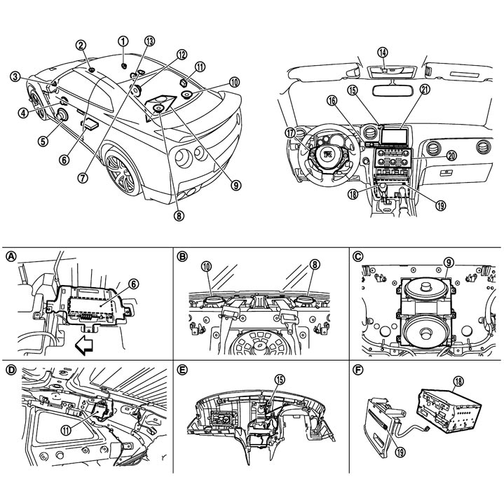
|
1. |
Tweeter RH |
2. |
Center speaker |
3. |
Tweeter LH |
|
4. |
Front door squawker LH |
5. |
Front door speaker LH |
6. |
BOSE amp. |
|
7. |
Satellite radio antenna |
8. |
Rear speaker LH |
9. |
Woofer |
|
10. |
Rear speaker RH |
11. |
Antenna amp. |
12. |
Front door speaker RH |
|
13. |
Front door squawker RH |
14. |
Microphone |
15. |
GPS antenna |
|
16. |
Multifunction switch |
17. |
Steering switch |
18. |
AV control unit |
|
19. |
Disk eject switch |
20. |
Preset switch |
21. |
Display unit |
|
A. |
Under front LH seat |
B. |
Inside rear parcel |
C. |
Inside rear seat back |
|
D. |
Inside rear pillar finisher LH |
E. |
Back of instrument panel |
F. |
Bottom side of cluster lid C |

|
: Front of vehicle |
|
|
|
|
Component Description
|
Part name |
Description |
|
AV CONTROL UNIT |
|
|
DISPLAY UNIT |
|
|
BOSE AMP. |
It inputs the power supply (BOSE amp. ON signal) and sound signal from the AV control unit and outputs the sound signal to each speaker. |
|
FRONT DOOR SPEAKER |
|
|
FRONT DOOR SQUAWKER |
|
|
REAR SPEAKER |
|
|
TWEETER |
|
|
CENTER SPEAKER |
|
|
WOOFER |
|
|
MULTIFUNCTION SWITCH |
|
|
DISK EJECT SWITCH |
It is connected to the preset switch with hardwire. The operation signal is transmitted to the AV control unit through the preset switch. |
|
PRESET SWITCH |
|
|
STEERING SWITCH |
|
|
MICROPHONE |
|
|
GPS ANTENNA |
GPS signal is received and is output to AV control unit. |
|
ANTENNA AMP. |
|
|
SATELLITE RADIO ANTENNA |
Satellite radio signal is received and transmitted to AV control unit. |