DIAGNOSIS SYSTEM (AV CONTROL UNIT)
BOSE AUDIO WITH NAVIGATION
Diagnosis Description
 MULTIFUNCTION SWITCH AND PRESET SWITCH SELF-DIAGNOSIS FUNCTION
The ON/OFF operation (continuity) of each switch in the multifunction switch and preset switch can be checked.
 Self-diagnosis mode
- Press both the preset switches “1” and “6” simultaneously within 10 seconds after turning the ignition switch from OFF to ACC and hold them for 3 seconds or more. Then release the switches. The buzzer sounds, all indicators of the centralized and preset switches illuminate, and the self-diagnosis mode starts.
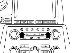
- The continuity of each switch at the ON position can be checked by pressing the switch. The buzzer sounds if the switch is normal.
Finishing self-diagnosis modeSelf-diagnosis mode is canceled when turning the ignition switch OFF.
MULTI AV SYSTEM ON BOARD DIAGNOSIS FUNCTION- Diagnosis is performed with the on board diagnosis and CONSULT‐III. Select an appropriate function due to the condition. Perform the on board diagnosis if it starts. Perform CONSULT‐III diagnosis if the on-board diagnosis does not start (e.g., the screen does not display anything, the multifunction switch does not function, etc.).
- In the on-board diagnosis, a multifunction switch operation starts the AV control unit diagnosis function and AV control unit performs a diagnosis for each system unit. Diagnosis results are displayed on the screen.
- In the CONSULT‐III diagnosis, a communication signal starts the AV control unit diagnosis function and AV control unit performs a diagnosis for each system unit.
ON BOARD DIAGNOSIS Description- The trouble diagnosis function has a self-diagnosis mode for conducting trouble diagnosis automatically and a confirmation/adjustment mode for operating manually.
- The self-diagnosis mode performs diagnoses on the AV control unit, connections between system components as well as connections between AV control unit and GPS antenna and between AV control unit and satellite radio antenna. Then it displays the diagnosis results on the display.
- The confirmation/adjustment mode allows the technician to check, modify or adjust the vehicle signals and set values, as well as to monitor the system error records and system communication status. The checking, modifying or adjusting generally require human intervention and judgment (the system cannot make judgment automatically).
On board diagnosis item|
Mode |
Description |
||
|
Self‐Diagnosis |
|
||
|
Confirmation/Adjustment |
Display Diagnosis |
The following check functions are available: color tone check by color bar display, light and shade check by gray scale display and touch panel calibration response check. |
|
|
Vehicle Signals |
Diagnosis of signals can be performed for vehicle speed, parking brake, lights, ignition switch and reverse. |
||
|
Speaker Test |
The connection of a speaker can be confirmed by test tone. |
||
|
Climate Control* |
Not used. |
||
|
Navigation |
Steering Angle Adjustment |
When there is a difference between the actual turning angle and the vehicle mark turning angle, it can be adjusted. |
|
|
Speed Calibration |
When there is a difference between the current location mark and the actual location, it can be adjusted. |
||
|
XM SAT Subscription Status |
The XM NavTraffic subscription status can be checked. |
||
|
Error History |
The system malfunction and the frequency when occurring in the past are displayed. When the malfunctioning item is selected, the time and place that the selected malfunction last occurred are displayed. |
||
|
Vehicle CAN Diagnosis |
The transmitting/receiving of CAN communication can be monitored. |
||
|
AV COMM Diagnosis |
The communication condition of each unit of Multi AV system can be monitored. |
||
|
Handsfree Phone |
The received volume adjustment of hands-free phone, microphone speaker check, and erase memory can be performed. |
||
|
Bluetooth |
The passkey and the device name can be checked and changed. |
||
|
SAT |
Change Channel |
Any necessary channels required to receive traffic information from the satellite radio system can be set. |
|
|
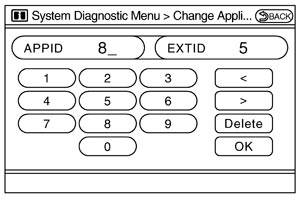
Change Application ID |
Any application ID's required to receive traffic information from the satellite radio system can be set. |
||
|
Diag |
Not used. |
||
|
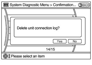
Delete Unit Connection Log |
Erase the connection history of unit and error history. |
||
|
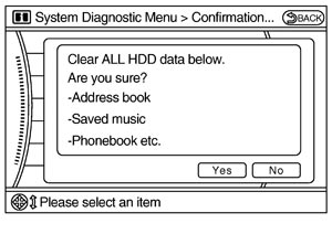
Initialize Settings |
Initializes the AV control unit memory. |
||
NOTE:
*:On-board self-diagnosis is not supported. Only CONSULT-III is supported.
STARTING PROCEDURE- 1.Start the engine.
- 2.Turn the audio system OFF.
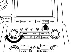
- 3.Turn the “VOL” dial either clockwise or counterclockwise for 40 clicks or more while pressing the “SETTING” button. (Beep sounds when starting the self-diagnosis mode.) Press the “BACK” switch and the initial system screen will be shown.
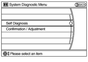
- 4.The trouble diagnosis initial screen is displayed, and then the items of “Self Diagnosis” and “Confirmation/Adjustment” can be selected.
 SELF-DIAGNOSIS MODE
- Start the self-diagnosis function and select “Self Diagnosis”.
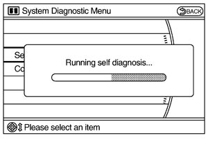
- Self-diagnosis subdivision screen is displayed, and the self-diagnosis mode starts.
- The bar graph visible on the center of the self-diagnosis subdivision screen indicates progress of the trouble diagnosis.
- Diagnosis results are displayed after the self-diagnosis is completed. The unit names and the connection lines are color-coded according to the diagnostic results.
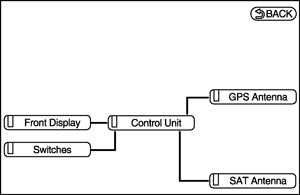
Diagnosis results Unit Connection line Normal Green Green Connection malfunction Gray Yellow Unit malfunction Note Red Green NOTE:- Only the control unit (AV control unit) is displayed in red.
- Replace AV control unit if “Self-Diagnosis did not run because of a control unit malfunction” is indicated. The symptom is AV control unit internal error. Refer to Removal and Installation.
- Only the control unit (AV control unit) is displayed in red.
- If multiple errors occur at the same time for a single unit, the screen switch colors are determined according to the following order of priority: red > gray.
- The comments of the self-diagnosis results can be viewed with a component in the diagnosis result screen.
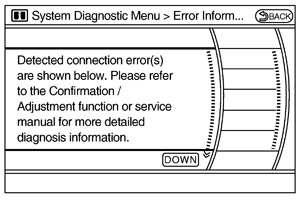
SELF-DIAGNOSIS RESULTSCheck the applicable display at the following table, and then repair the malfunctioning parts.
Self-diagnosis result chart| Area with yellow connection lines | Description | Possible malfunction location / Action to take |
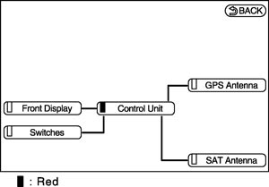 | Malfunction is detected in AV control unit power supply and ground circuits. | Check AV control unit power supply and ground circuits. When detecting no malfunction in those components, replace AV control unit. |
| “Self‐Diagnosis did not run because of a control unit malfunction” | ||
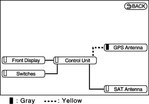 | GPS antenna connection malfunction is detected. | GPS antenna. |
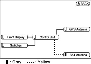 | Poor connection is detected in satellite radio antenna. |
|
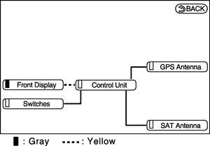 |
| Communication circuits between AV control unit and display unit. |
CONFIRMATION/ADJUSTMENT MODE- 1.Start the diagnosis function and select “Confirmation/Adjustment”. The confirmation/adjustment mode indicates where each item can be checked or adjusted.
- 2.Select each switch on the “Confirmation/Adjustment Mode” screen to display the relevant trouble diagnosis screen. Press the “BACK” switch to return to the initial Confirmation/Adjustment Mode screen.
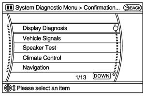 Display Diagnosis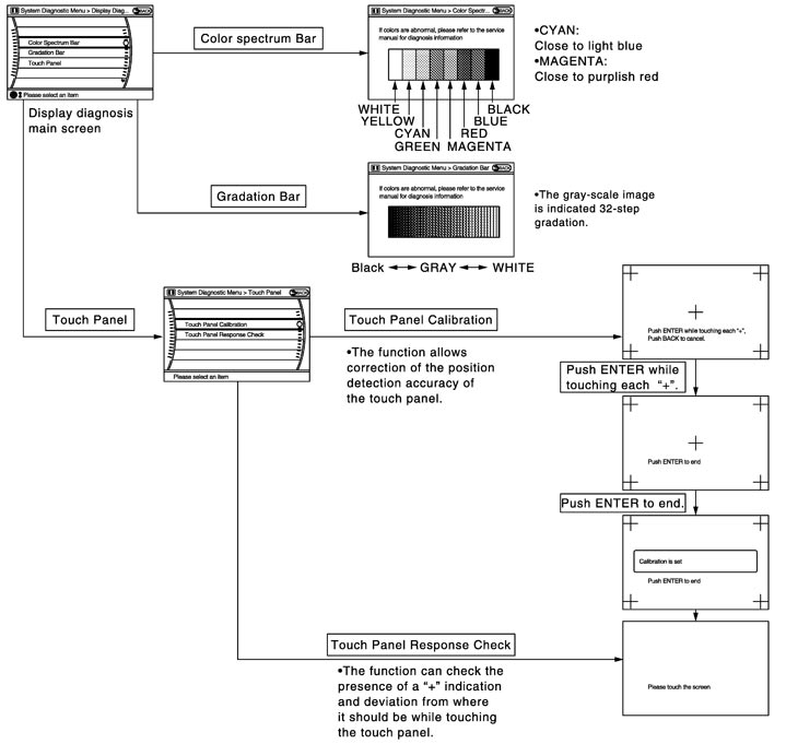
The tint of the color bar indication is as per the following list if RGB signal error is detected.
| R (red) signal error | : Light blue (Cyan) tint |
| G (green) signal error | : Purple (Magenta) tint |
| B (blue) signal error | : Yellow tint |
Vehicle SignalsA comparison check can be made of each actual vehicle signal and the signals recognized by the system.
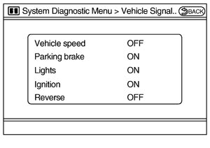
| Diagnosis item | Display | Vehicle status | Remarks |
| Vehicle speed | ON | Vehicle speed > 0 km/h (0 MPH) | Changes in indication may be delayed. This is normal. |
| OFF | Vehicle speed = 0 km/h (0 MPH) | ||
| Parking brake | ON | Parking brake is applied. | |
| OFF | Parking brake is released. | ||
| Lights | ON | Light switch ON | — |
| OFF | Light switch OFF | ||
| Ignition | ON | Ignition switch ON | — |
| OFF | Ignition switch in ACC position | ||
| Reverse | ON | Shift the selector lever to “R” position | Changes in indication may be delayed. This is normal. |
| OFF | Shift the selector lever other than “R” position |
Speaker TestSelect “SPEAKER DIAGNOSIS” to display the Speaker Diagnosis screen. Press “Start” to generate a test tone in a speaker. Press “Start” to generate a test tone in the next speaker. Press “End” to stop the test tones.
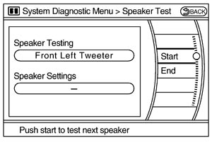
NOTE:
The frequency of test tone emitted from each speaker is as follows.| Tweeter | : 3 kHz |
| Front speaker | : 300 Hz |
| Rear speaker | : 1 kHz |
Climate ControlOn-board self-diagnosis is not supported. Only CONSULT-III is supported. Refer to CONSULT-III Function for details.
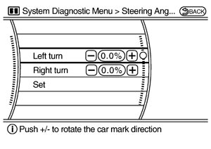
NavigationSTEERING ANGLE ADJUSTMENT
The steering angle output value detected with the gyroscope is adjusted.
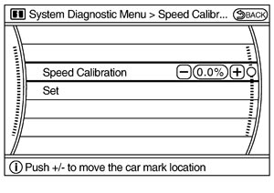
SPEED CALIBRATION
During normal driving, distance error caused by tire wear and tire pressure change is automatically adjusted for by the automatic distance correction function. This function, on the other hand, is for immediate adjustment, in cases such as driving with tire chain fitted on tires.
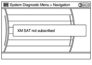
XM SAT SUBSCRIPTION STATUS
The XM NavTraffic subscription status can be checked.
 Error History
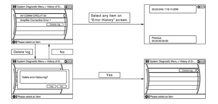
The self-diagnosis results are judged depending on whether any error occurs from when “Self-diagnosis” is selected until the self-diagnosis results are displayed.
However, the diagnosis results are judged normal if an error has occurred before the ignition switch is turned ON and then no error has occurred until the self-diagnosis start. Check the “Error Record” to detect any error that may have occurred before the self-diagnosis start because of this situation.
The error record displays the time and place of the most recent occurrence of that error. However, take note of the following points.
- If there is a malfunction with the GPS antenna circuit board in the AV control unit, the correct date and time of occurrence may not be able to be displayed.
- Place of the error occurrence is represented by the position of the current location mark at the time an error occurred. If current location mark has deviated from the correct position, then the place of the error occurrence cannot be located correctly.
- The frequency of occurrence is displayed in a count up manner. The actual count up method differs depending on the error item.
- The counter resets to 0 if an error occurs when IGN switch is turned ON. The counter increases by 1 if the condition is normal at a next IGN ON cycle.
- The counter upper limit is 39. Any counts exceeding 39 are ignored.“ The counter can be reset (no error record display) with the “Delete log” switch or CONSULT‐III.
- The counter increases by 1 if an error occurs when IGN switch is ON. The counter will not decrease even if the condition is normal at the next IGN ON cycle.
- The counter upper limit is 50. Any counts exceeding 50 are ignored. “ The counter can be reset (no error record display) with the “Delete log” switch or CONSULT‐III.
| Display type of occurrence frequency | Error history display item |
| Count up method A | CAN communication line, control unit (CAN), AV communication line, control unit (AV communication) |
| Count up method B | Other than the above |
Error item
Some error items may be displayed simultaneously according to the cause. If some error items are displayed simultaneously, the detection of the cause can be performed by the combination of display items
| Error item | Description | Possible malfunction factor/Action to take |
| CAN COMM CIRCUIT | CAN communication malfunction is detected. | Perform diagnosis with CONSULT‐III, and then repair the malfunctioning parts according to the diagnosis results. Refer to CONSULT-III Function. |
| CONTROL UNIT (CAN) | CAN initial diagnosis malfunction is detected. | Replace the AV control unit. |
| CONTROL UNIT (AV) | AV communication circuit initial diagnosis malfunction is detected. | |
| FLASH‐ROM Error Of Control Unit | AV control unit malfunction is detected. | |
| Connection Of Gyro | ||
| ACCEL SENSOR CONN Error | ||
| CAN Controller Memory Error | ||
| Bluetooth Module Connection Error | ||
| HDD CONN Error | ||
| HDD READ Error | ||
| HDD WRITE Error | ||
| HDD COMM Error | ||
| HDD ACCESS Error | ||
| DSP CONN Error | ||
| DSP COMM Error | ||
| XM SERIAL COMM Error | ||
| Internal Communication Error | AV control unit power supply and ground circuits. | |
| GPS Communication Error | GPS malfunction is detected. | An intermittent error caused by strong radio interference may be detected unless any symptom (GPS reception error, etc.) occurs. Replace the AV control unit if the malfunction occurs constantly. |
| GPS ROM Error | ||
| GPS RAM Error | ||
| GPS RTC Error | ||
| Front Display Connection Error |
|
|
| GPS Antenna Error | GPS antenna connection malfunction is detected. | GPS antenna. |
| XM Antenna Connection Error | Poor connection is detected in satellite radio antenna. |
|
|
| AV control unit power supply and ground circuits. |
|
|
|
Vehicle CAN Diagnosis- CAN communication status and error counter is displayed.
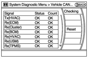
- The error counter displays “OK” if any malfunction was not detected in the past and displays “0” if a malfunction is detected. It increases by 1 if the condition is normal at the next ignition switch ON cycle. The upper limit of the counter is 39.
- The error counter is erased if “Reset” is pressed.
Signal
(Communication)Status
(Current)Counter
(Past)Tx (HVAC) OK / UNKWN OK / 0 - 39 Rx (ECM) OK / UNKWN OK / 0 - 39 Rx (Cluster) OK / UNKWN OK / 0 - 39 Rx (BCM) OK / UNKWN OK / 0 - 39 Rx (HVAC) OK / UNKWN OK / 0 - 39 Rx (USM) OK / UNKWN OK / 0 - 39 Rx (TPMS) OK / UNKWN OK / 0 - 39 Rx (STRG) OK / UNKWN OK / 0 - 39 Rx (VDC) OK / UNKWN OK / 0 - 39
AV COMM Diagnosis- Displays the communication status between AV control unit (master unit) and each unit.
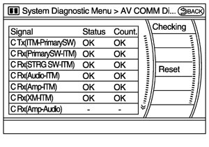
- The error counter displays “OK” if any malfunction was not detected in the past and displays “0” if a malfunction is detected. It increases by 1 if the condition is normal at the next ignition switch ON cycle. The upper limit of the counter is 39.
- The error counter is erased if “Reset” is pressed.
Items Status
(Current)Counter
(Past)C Tx (ITM–PrimarySW) OK / UNKWN OK / 0 – 39 C Rx (PrimarySW–ITM) OK / UNKWN OK / 0 – 39 C Rx (STRG SW–ITM) OK / UNKWN OK / 0 – 39 C Rx (Audio–ITM) OK / UNKWN OK / 0 – 39 C Rx (Amp–ITM) OK / UNKWN OK / 0 – 39 C Rx (XM–ITM) OK / UNKWN OK / 0 – 39 C Rx (Amp–Audio) — — C Tx (Audio–ITM) OK / UNKWN OK / 0 – 39 NOTE:- Any units with “—” displayed have no history of vehicle connection.
- “Audio” and “Amp” indicate the same status because “Amp” indicates the status of the amplifier integrated in the AV control unit.
- “STRG SW”, “Amp” and “XM” indicate the same status as “Audio”.
- Any units with “—” displayed have no history of vehicle connection.
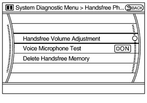
Hands‐Free PhoneThe hands-free phone reception volume adjustment, microphone and speaker test, and memory erase functions are also available.
 Bluetooth
Passkey confirmation/change
- The passkey of Bluetooth can be confirmed and changed.
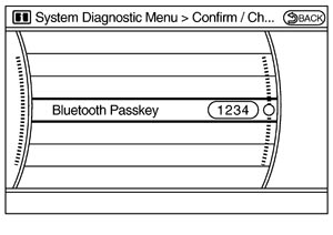
- The passkey can be changed by four digits within 0 to 9.
- The device name of Bluetooth can be confirmed and changed.
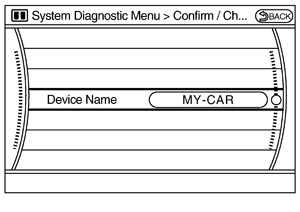
- The device name can be changed by sixteen digits within A to Z (small character can be used) and - (hyphen).
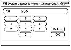
SAT - Change Channel
- Any necessary channels required to receive traffic information from the satellite radio system can be set.
- Change Application ID
- Any application ID'‐s required to receive traffic information from the satellite radio system can be set.
Delete Unit Connection LogDeletes any unit connection records and error records from the AV control unit memory. (Clear the records of the unit that has been removed.)
 Initialize Settings
Deletes data stored in HDD.
CONSULT-III Function
CONSULT-III FUNCTIONSCONSULT-III performs the following functions via the communication with the AV control unit.
| Diagnosis mode | Description |
| Ecu Identification | The part number of AV control unit can be checked. |
| Self Diagnostic Result | Performs a diagnosis on the AV control unit and a connection diagnosis for the communication circuit of the Multi AV system, and displays the current and past malfunctions collectively. |
| Data Monitor | The diagnosis of vehicle signal that is input to the AV control unit can be performed. |
AV COMMUNICATIONWhen “AV communication” of “CAN Diag Support Monitor” is selected, the following function will be performed.
| AV communication | AV&NAVI C/U | Displays the communication status from AV control unit to each unit as well as the error counter. |
| AUDIO | Displays the AV control unit communication status and the error counter. |
ECU IDENTIFICATIONThe part number of AV control unit is displayed.
SELF DIAGNOSIS RESULT- In CONSULT-III self-diagnosis, self-diagnosis results and error history are displayed collectively.
- The current malfunction indicates “CRNT”. The past malfunction indicates “PAST”.
- The timing is displayed as “0” if any of the error codes [U1000], [U1010], [U1300] and [U1310] is detected. The counter increases by 1 if the condition is normal at the next ignition switch ON cycle.
Self-diagnosis results display item|
Error item |
Description |
Possible malfunction factor/Action to take |
|
CAN COMM CIRCUIT[U1000] |
CAN communication malfunction is detected. |
Refer to Diagnosis Procedure. |
|
CONTROL UNIT (CAN) [U1010] |
CAN initial diagnosis malfunction is detected. |
Replace the AV control unit. |
|
CONTROL UNIT (AV) [U1310] |
AV communication circuit initial diagnosis malfunction is detected. |
|
|
Control Unit FLASH‐ROM [U1200] |
AV control unit malfunction is detected. |
|
|
Gyro NO CONN [U1201] |
||
|
G-SENSOR NO CONN[U1202] |
||
|
CAN CONT [U1216] |
||
|
BLUETOOTH CONN [U1217] |
||
|
HDD CONN [U1218] |
||
|
HDD READ [U1219] |
||
|
XM SERIAL COMM [U1220] |
||
|
HDD WRITE [U121A] |
||
|
HDD COMM [U121B] |
||
|
HDD ACCESS [U121C] |
||
|
DSP CONN [U121D] |
||
|
DSP COMM [U121E] |
||
|
INTERNAL COMM [U121F] |
AV control unit power supply and ground circuits. |
|
|
GPS COMM [U1204] |
GPS malfunction is detected. |
An intermittent error caused by strong radio interference may be detected unless any symptom (GPS reception error, etc.) occurs. Replace the AV control unit if the malfunction occurs constantly. |
|
GPS ROM [U1205] |
||
|
GPS RAM [U1206] |
||
|
GPS RTC [U1207] |
||
|
FRONT DISP CONN [U1243] |
|
|
|
GPS ANTENNA CONN [U1244] |
GPS antenna connection malfunction is detected. |
GPS antenna. |
|
XM ANTENNA CONN [U1258] |
Poor connection is detected in satellite radio antenna. |
|
|
|
AV control unit power supply and ground circuits. |
|
|
|
DATA MONITOR ALL SIGNALS- Displays the status of the following vehicle signals inputted into the AV control unit.
- For each signal, actual signal can be compared with the condition recognized on the system.
Display Item Display Vehicle status Remarks VHCL SPD SIG On Vehicle speed >0 km/h (0 MPH) Changes in indication may be delayed. This is normal. Off Vehicle speed =0 km/h (0 MPH) PKB SIG On Parking brake is applied. Off Parking brake is released. ILLUM SIG On Block the light beam from the auto light optical sensor when the light switch is ON. — Off Expose the auto light optical sensor to light when the light switch is OFF or ON. IGN SIG On Ignition switch ON Off Ignition switch in ACC position REV SIG On Selector lever in R position Changes in indication may be delayed. This is normal. Off Selector lever in any position other than R
SELECTION FROM MENUAllows the technician to select which vehicle signals should be displayed and displays the status of the selected vehicle signals.
| Item to be selected | Description |
| VHCL SPD SIG | The same as when “ALL SIGNALS” is selected. |
| PKB SIG | |
| ILLUM SIG | |
| IGN SIG | |
| REV SIG |