DISPLAY UNIT
BOSE AUDIO WITH NAVIGATION
Reference Value
 TERMINAL LAYOUT
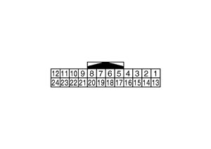 PHYSICAL VALUES
|
Terminal (Wire color) |
Description |
Condition |
Reference value (Approx.) |
|||
|
+ |
– |
Signal name |
Input/Output |
|||
|
1 (B) |
Ground |
GND |
— |
Ignition switch ON |
— |
0 V |
|
2 (Y) |
Ground |
Battery power supply |
Input |
Ignition switch OFF |
— |
Battery voltage |
|
3 (P) |
Ground |
ACC power supply |
Input |
Ignition switch ACC |
— |
Battery voltage |
|
4 |
— |
Shield |
— |
— |
— |
— |
|
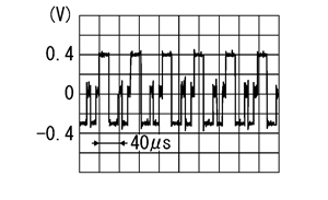
6 (G) |
Ground |
RGB signal (G: green) |
Input |
Ignition switch ON |
Start confirmation/adjustment mode, and then display color bar by selecting “Color Spectrum Bar” on DISPLAY DIAGNOSIS screen. |
|
|
7 |
— |
Shield |
— |
— |
— |
— |
|
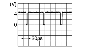
8 (R) |
Ground |
Horizontal synchronizing (HP) signal |
Output |
Ignition switch ON |
— |
|
|
9 (W) |
Ground |
RGB area (YS) signal |
Input |
Ignition switch ON |
At RGB image is displayed |
5 V |
|
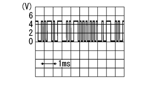
11 (BR) |
Ground |
Communication signal (CONT→DISP) |
Input |
Ignition switch ON |
When adjusting displaybrightness. |
|
|
13 (B) |
Ground |
GND |
— |
Ignition switch ON |
— |
0 V |
|
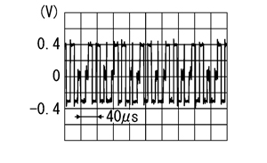
17 (R) |
Ground |
RGB signal (R: red) |
Input |
Ignition switch ON |
Start confirmation/adjustment mode, and then display color bar by selecting “Color Spectrum Bar” on DISPLAY DIAGNOSIS screen. |
|
|
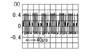
18 (B) |
Ground |
RGB signal (B: blue) |
Input |
Ignition switch ON |
Start confirmation/adjustment mode, and then display color bar by selecting “Color Spectrum Bar” on DISPLAY DIAGNOSIS screen. |
|
|
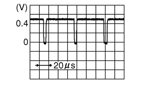
19 (W) |
Ground |
RGB synchronizing signal |
Input |
Ignition switch ON |
— |
|
|
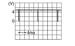
20 (B) |
Ground |
Vertical synchronizing (VP) signal |
Output |
Ignition switch ON |
— |
|
|
21 |
— |
Shield |
— |
— |
— |
— |
|
22 (Y) |
Ground |
Communication signal (DISP→CONT) |
Output |
Ignition switch ON |
When adjusting displaybrightness. |
|
|
23 |
— |
Shield |
— |
— |
— |
— |
Wiring Diagram - BOSE AUDIO WITH NAVIGATION SYSTEM -
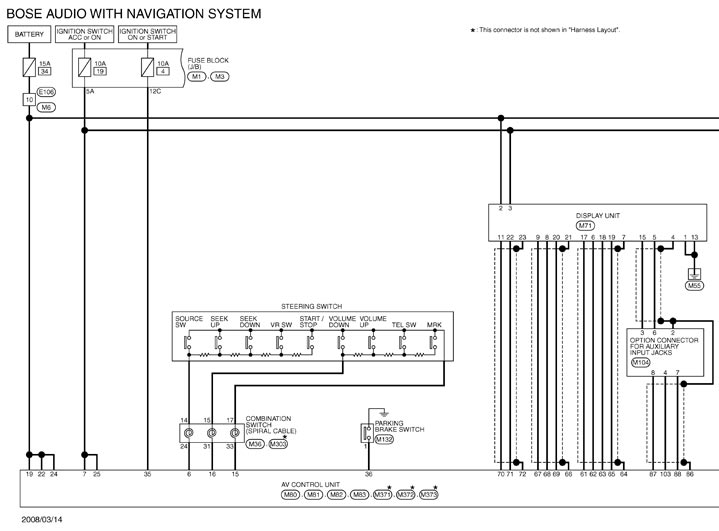
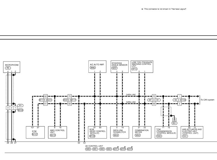
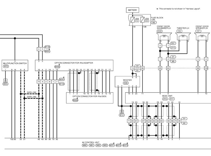
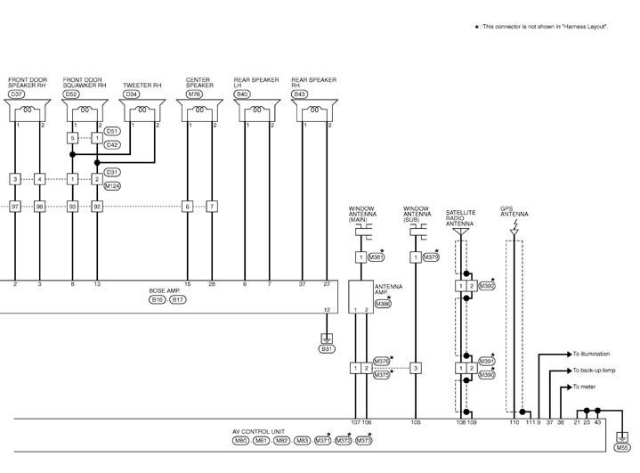
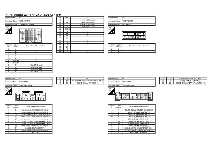
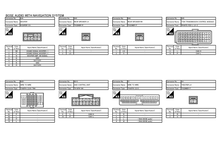
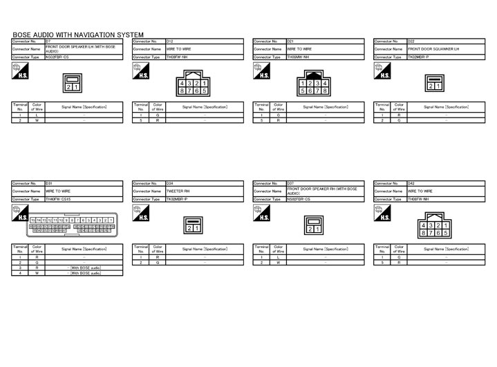
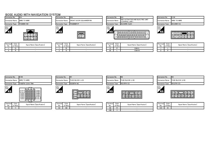
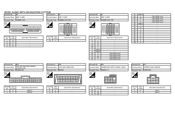
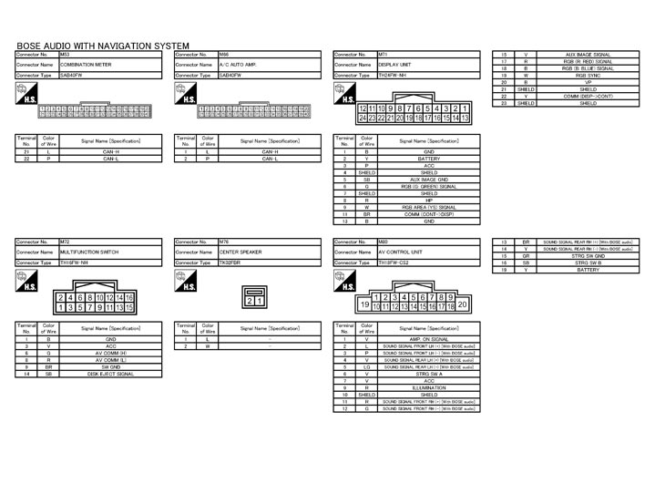
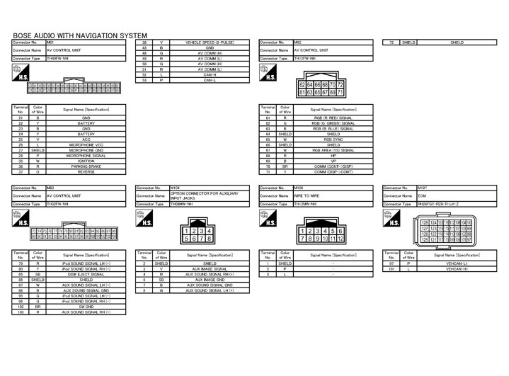
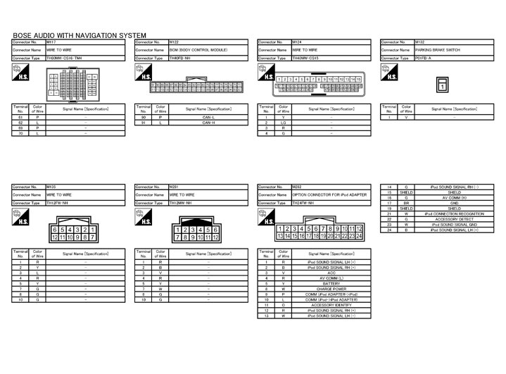
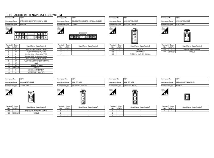
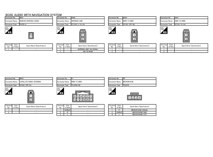
NOTE:
The name MULTIFUNCTION SWITCH indicates the integration of PRESET SWITCH and MULTIFUNCTION SWITCH virtually.