MULTI AV SYSTEM SYMPTOMS
BOSE AUDIO WITH NAVIGATION
 RELATED TO NAVIGATION
 Trouble diagnosis chart by symptom
|
Symptoms |
Check items |
Possible malfunction location/Action to take |
|
The multifunction switch and preset switch cannot be operated |
Only the specified switch cannot be operated |
|
|
Preset switch does not work |
The multifunction switch can be operated |
Perform self-diagnosis of CONSULT‐III. Refer to CONSULT-III Function. |
|
Audio switch does not work |
Steering switch does not work |
Perform self-diagnosis of CONSULT‐III. Refer to CONSULT-III Function. |
|
Fuel economy display and vehicle setting operation is abnormal |
There is a malfunction in the CONSULT‐III self-diagnosis result |
Perform detected DTC self-diagnosis |
|
There is no malfunction in the self-diagnosis results |
AV control unit power supply and ground circuit (IGN). Refer to Diagnosis Procedure. |
|
|
The multifunction meter display is malfunctioning |
There is a malfunction in the CONSULT‐III self-diagnosis result |
Perform detected DTC self-diagnosis. |
|
There is no malfunction in the self-diagnosis results |
AV control unit power supply and ground circuit (IGN). Refer to Diagnosis Procedure. |
|
|
Guide sound is not heard. |
On the setting display select “system sound (guide sound volume, etc.),”and confirm that guide sound is ON. |
Replace the AV control unit. Refer to Removal and Installation. |
RELATED TO HANDS‐FREE PHONE- When receiving a vehicle with a hands-free related malfunction, check that the cell phone is capable of hands -free before starting diagnoses.
- There is a case that malfunction occurs due to the version change of the phone type, etc. even though it is a corresponding type. Therefore, confirm it by changing the cellular phone to another corresponding type phone, and check that it operates normally. It is necessary to distinguish whether the cause is the vehicle or cellular phone.
Simple check for BluetoothTM communicationIf cellular phone and AV control unit cannot be connected with BluetoothTM communication, following procedure allows the technician to judge which device has malfunction.
- 1.Turn on a cellular phone, not connecting BluetoothTM communication.
- 2.Start CONSULT‐III, then start Windows®.
- 3.Set CONSULT‐III near a cellular phone.
- 4.When operated BluetoothTM registration by cellular phone, check if CONSULT‐III* would be displayed on the device name.
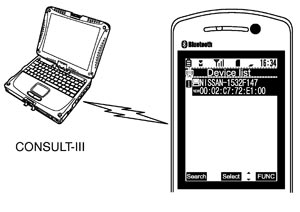
(If other BluetoothTM device is located near cellular phone, a name of the device would be displayed also.)
NOTE:
*:Displayed device name is “NISSAN‐ ”.
”.- If no device name is displayed, cellular phone is malfunctioning. Repair the cellular phone first, then perform diagnosis.
- If CONSULT-III is displayed on device name, cellular phone is normal. Perform diagnosis as per the following table.
Trouble diagnosis chart by symptom|
Symptoms |
Check items |
Possible malfunction location / Action to take |
|
Does not recognize cellular phone connection. (no connection is displayed on the display at the guide) |
Repeat the registration of cellular phone. |
AV control unit malfunction. Replace AV control unit. Refer to Exploded View. |
|
Hands‐free phone cannot be established. |
|
AV control unit malfunction. Replace AV control unit. Refer to Exploded View. |
|
The party's voice cannot be heard by hands‐free phone. |
— |
AV control unit malfunction. Replace AV control unit. Refer to Exploded View. |
|
Originating sound is not heard by the party with hands‐free phone communication. |
Sound operation function is normal. |
AV control unit malfunction. Replace AV control unit. Refer to Exploded View. |
|
Sound operation function does not work. |
Microphone signal circuit malfunction. Refer to Diagnosis Procedure. |
RELATED TO RGB IMAGE Trouble diagnosis chart by symptom|
Symptoms |
Check items |
Possible malfunction location / Action to take |
|
RGB image is not shown. |
|
Perform CONSULT‐III self-diagnosis. Refer to CONSULT - III Function (MULTI AV). |
|
AV control unit power supply and ground circuit malfunction. Refer to Diagnosis Procedure. |
|
|
Color of RGB image is not proper. |
Light blue (Cyan) tint. |
RGB signal (R: red) circuit malfunction between AV control unit and display unit. Refer to Diagnosis Procedure. |
|
Purple (Magenta) tint. |
RGB signal (G: green) circuit malfunction between AV control unit and display unit. Refer to Diagnosis Procedure. |
|
|
Screen looks yellowish. |
RGB signal (B: blue) circuit malfunction between AV control unit and display unit. Refer to Diagnosis Procedure. |
|
|
RGB screen is rolling. |
— |
RGB synchronizing signal circuit malfunction between AV control unit and display unit. Refer to Diagnosis Procedure. |
RELATED TO VOICE CONTROL Trouble diagnosis chart by symptom|
Symptoms |
Check items |
Probable malfunction location |
|
The voice cannot be controlled even if the voice control screen is displayed. |
Voice sounds at “Voice Microphone Test” of Confirmation/Adjustment mode. |
AV control unit malfunction. Replace AV control unit. Refer to Exploded View. |
|
Voice does not sound at “Voice Microphone Test” of Confirmation/Adjustment mode. |
Microphone circuit malfunction. Refer to Diagnosis Procedure. |
|
|
The voice cannot be controlled (Voice control screen is not displayed). |
Regarding the steering switch, “SOURCE”, “SEEK UP”, “SEEK DOWN”, and “START/STOP” but not “ ”. ”. |
Steering switch malfunction. Replace steering switch. Refer to Exploded View. |
|
Regarding steering switch, “SOURCE”, “SEEK UP”, “SEEK DOWN”, “”, and “START/STOP” do not function. |
Steering switch signal A circuit malfunction. Refer to Diagnosis Procedure. |
|
|
All steering switches do not work. |
Steering switch signal GND circuit malfunction. Refer to Diagnosis procedure . |
RELATED TO AUDIO Trouble diagnosis chart by symptom|
Symptoms |
Check items |
Possible malfunction location / Action to take |
|
The CD cannot be removed. |
— |
Disk eject signal circuit malfunction. Refer to Diagnosis Procedure. |
|
The preset switch cannot be operated |
|
AV control unit power supply and ground circuit. Refer to Diagnosis Procedure. |
|
Audio sound is not heard. |
No sound from all speakers. |
|
|
Sound is not heard from woofer. |
|
|
|
Sound is not heard from center speaker. |
Sound signal center speaker circuit. |
|
|
Sound is heard only from specific places (RH front, RH rear, LH front and LH rear). |
Sound signal circuit of suspect system. |
|
|
Satellite radio is not received. |
There is malfunction in the CONSULT‐III self‐diagnosis result. |
Perform CONSULT‐III self-diagnosis. Refer to CONSULT - III Function (MULTI AV). |
|
There is no malfunction in the CONSULT‐III self‐diagnosis result. |
Perform the following inspection procedure.
|
|
|
AM/FM radio is not received. |
Other audio sounds are normal. |
|
MULTIFUNCTION METERTrouble diagnosis chart by symptom
|
Symptoms |
Check items |
Possible malfunction location / Action to take |
|
|
The multifunction meter cannot be displayed |
There is a malfunction in the CONSULT‐III self-diagnosis result |
Perform detected DTC self-diagnosis |
|
|
There is no malfunction in the self-diagnosis results |
AV control unit power supply and ground circuit (IGN) Refer to Diagnosis Procedure. |
||
|
Only a particular item cannot be displayed |
“COOLANT TEMP” display is malfunctioning |
|
|
|
“ENGINE OIL TEMP” display is malfunctioning |
|
||
|
“ENGINE OIL PRESSURE” display is malfunctioning |
|
||
|
“TRANS OIL TEMP” display is malfunctioning |
|
||
|
“TRANS OIL PRESSURE” display is malfunctioning |
|
||
|
“BOOST” display is malfunctioning |
|
||
|
“SPEED” display is malfunctioning |
|
||
|
The multifunction meter cannot be displayed |
Only a particular item cannot be displayed |
“FUEL / RANGE” display is malfunctioning |
|
|
“FUEL FLOW” display is malfunctioning |
|
||
|
“FUEL ECON.” display is malfunctioning |
|
||
|
“TORQUE SPLIT” display is malfunctioning |
|
||
|
“ACCEL BRAKING G” display is malfunctioning |
|
||
|
“CORNERING G” display is malfunctioning |
|
||
|
“TOTAL G” display is malfunctioning |
|
||
|
“CLOCK” display is malfunctioning |
GPS antenna circuit |
||
|
“ACCEL PEDAL” display is malfunctioning |
|
||
|
“BRAKE PEDAL” display is malfunctioning |
|
||
|
“STEERING” display is malfunctioning |
|
||
|
The multifunction meter cannot be displayed |
Only a particular item cannot be displayed |
“GEAR EFFICIENCY” display is malfunctioning |
|
|
“FUEL EFFICIENCY ” display is malfunctioning |
|
||
|
“DRIVER'S NOTES” display is malfunctioning |
AV control unit. |
||
|
“STOP WATCH” display is malfunctioning |
AV control unit. |
||
RELATED TO STEERING SWITCH Trouble diagnosis chart by symptom|
Symptoms |
Probable malfunction location |
|
All the steering switch are inoperative. |
Steering switch signal ground circuit. Refer to Diagnosis procedure . |
|
Only the specified switch (1) cannot be operated |
Replace the steering switch. Refer to Removal and Installation. |
|
Regarding the steering switch, “SOURCE”, “SEEK UP”, “SEEK DOWN”, “”, “START / STOP” do not function |
Steering switch signal A circuit. Refer to Diagnosis Procedure. |
Regarding the steering switch, “MRK”, “VOL UP”, “VOL DOWN”, “ ” do not function ” do not function |
Steering switch signal B circuit. Refer to Diagnosis Procedure. |