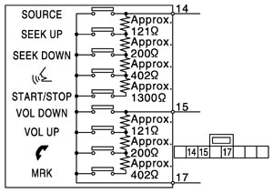
STEERING SWITCH SIGNAL GND CIRCUIT
BOSE AUDIO WITH NAVIGATION
Description
Steering switch power supply and signal ground circuit.
Diagnosis procedure
 1.Check continuity of steering switch signal ground circuit
Component Inspection
Measure the resistance between the steering switch connector terminals 14 to 17 and 15 to 17.
Standard
| Between terminals 14 – 17 | |
| START / STOP switch ON | : 1982 – 2063 Ω |
 switch ON switch ON | : 708 – 737 Ω |
| SEEK DOWN switch ON | : 314 – 327 Ω |
| SEEK UP switch ON | : 118 – 123 Ω |
| SOURCE switch ON | : 1 Ω or less |
| Between terminals 15 – 17 | |
| MRK switch ON | : 708 – 737 Ω |
 switch ON switch ON | : 314 – 327 Ω |
| VOL UP switch ON | : 118 – 123 Ω |
| VOL DOWN switch ON | : 1 Ω or less |