HEATER & COOLING UNIT ASSEMBLY
Removal and Installation
 REMOVAL
- 1.Use a refrigerant collecting equipment (for HFC‐134a) to discharge the refrigerant.
- 2.Drain engine coolant from cooling system. Refer to Draining.
- 3.Remove cowl top cover. Refer to Exploded View.
- 4.Remove engine cover. Refer to Exploded View.
- 5.Remove air pump hose from air pump pipe. Refer to Exploded View (GT-R certified NISSAN dealer).
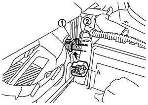
- 6.Disconnect one-touch joint between low‐pressure pipe 1 (1) and low‐pressure flexible hose with disconnector (SST: 9253089916) (A).
■ CAUTION ■
Cap or wrap the joint of the cooler piping with suitable material such as vinyl tape to avoid the entry of air.- 7.Disconnect one-touch joint between high‐pressure pipe 2 (2) and high‐pressure pipe 3 with disconnector (SST: 9253089908).
■ CAUTION ■
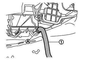
Cap or wrap the joint of the cooler piping with suitable material such as vinyl tape to avoid the entry of air.- 8.Remove clamp (A), and then disconnect drain hose (1) from heater & cooling unit assembly.
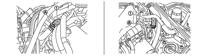
- 9.Remove clamps (A), and then disconnect heater hoses (1).
- 10.Remove front wiper drive assembly. Refer to Exploded View.
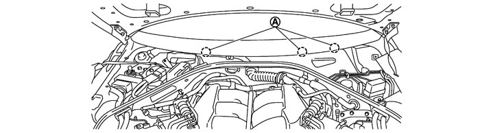
- 11.Remove steering member mounting bolts (A).
- 12.Remove instrument panel assembly. Refer to Exploded View.
- 13.Remove front defroster nozzle. Refer to Exploded View.
- 14.Remove blower unit. Refer to Exploded View.
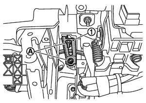
- 15.Remove mounting bolt (A), and then remove brake pedal stay (1).
- 16.Remove mounting bolts (A), and then remove SMJ from steering member (1).
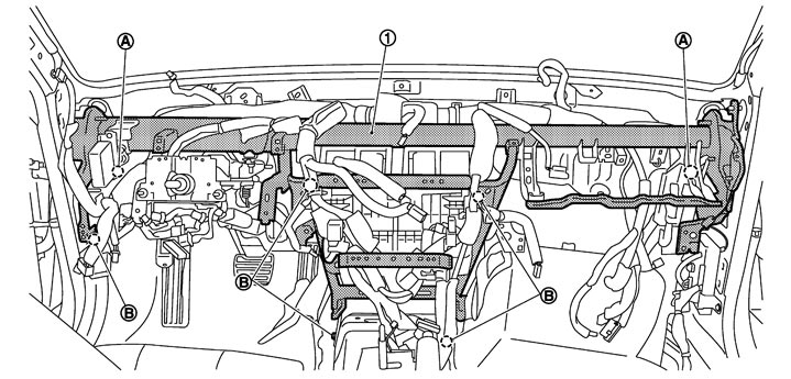
- 17.Remove mounting bolts (B) from steering member.
- 18.Remove tire pressure warning control unit. Refer to Exploded View (GT-R certified NISSAN dealer).
- 19.Remove ground bolts from steering member.
- 20.Remove steering column from steering member, and steering column a position without the hindrance for work. Refer to Exploded View.
- 21.Remove harness connector and clips of vehicle harness from steering member.
- 22.Remove door assembly LH and RH. Refer to Exploded View.
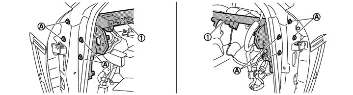
- 23.Remove mounting bolts (A) from steering member (1).
- 24.Remove steering member, and then remove heater & cooling unit assembly.
INSTALLATIONInstallation is basically the reverse order of removal.
■ CAUTION ■
- Replace O‐rings with new ones. Then apply compressor oil to them when installing.
- Female‐side piping connection is thin and easy to deform. Slowly insert the male‐side piping straight in axial direction.
- Insert piping securely until a clicks is heard.
- After piping connection is completed, pull male‐side piping by hand to make sure that connection does not come loose.
- Check for leakages when recharging refrigerant.
NOTE:
- Refer to Refilling when filling radiator with engine coolant.
- Recharge the refrigerant.
 STEERING MEMBER
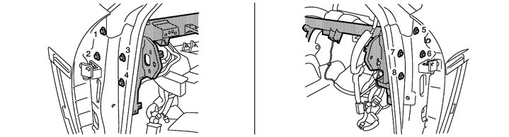
Tighten mounting bolts in numerical order as shown in the figure.
Inspection
CHECK CLEARANCE BETWEEN BODY AND STEERING MEMBER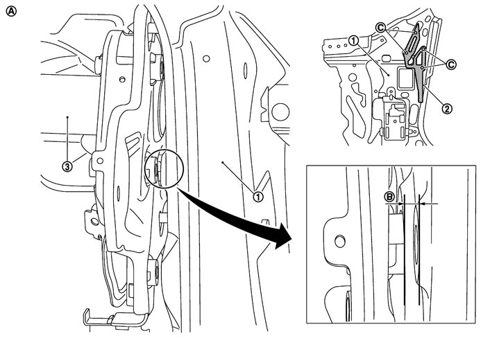
|
1. |
Upper rear hoodledge (RH) |
2. |
Shim |
3. |
Steering member |
|
A. |
Passenger side |
B. |
Clearance |
C. |
Measuring point |
- 1.Tighten the driver side steering member mounting bolts to the specified torque. Refer to Exploded View (GT-R certified NISSAN dealer).
■ CAUTION ■
Install the steering member with the shim assembled if the shim is installed between the upper rear hoodledge (RH) and steering member when removing the steering member. - 2.Measure the clearance between upper rear hoodledge (RH) and steering member using a feeler gauge.
- Perform the measurement at the 4 measuring points.
Standard : 0 – 0.6 mm - Select the shim from the table below so that the clearance is within the standard if it is outside the standard. Then, install it between upper rear hoodledge (RH) and steering member.
Measuring result (mm) Shim thickness (mm) Shim part number 0.7 – 1.2 0.6 31438 JF00A 1.3 – 1.6 1.2 31438 JF00B 1.7 – 2.3 1.6 31438 JF00C 2.4 – 3.4 2.3 31438 JF00D
- 3.Install the passenger side steering member mounting bolts after checking that the values are within the standard.