HOW TO READ WIRING DIAGRAMS
Connector Symbols
Most of connector symbols in wiring diagrams are shown from the terminal side.
- Connector symbols shown from the terminal side are enclosed by a single line and followed by the direction mark.
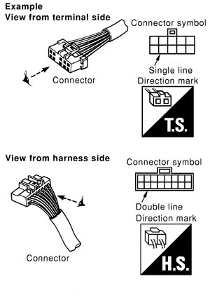
- Connector symbols shown from the harness side are enclosed by a double line and followed by the direction mark.
- Certain systems and components, especially those related to OBD, may use a new style slide-locking type harness connector. For description and how to disconnect, refer to PG section, “Description”, “HARNESS CONNECTOR”.
- Male and female terminals
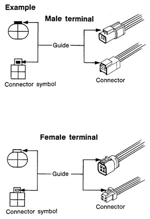
Connector guides for male terminals are shown in black and female terminals in white in wiring diagrams.
Sample/Wiring Diagram -Example-
- For detail, refer to following Description.
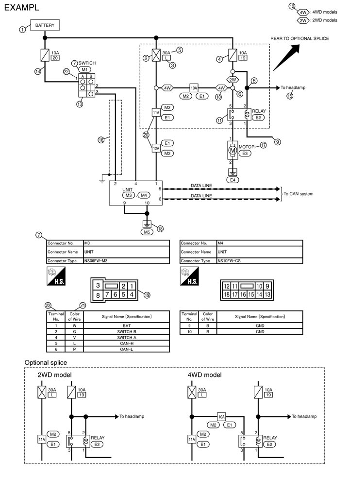
Description
|
Number |
Item |
Description |
|
|
1 |
Power supply |
|
|
|
2 |
Fusible link |
|
|
|
3 |
Number of fusible link/fuse |
|
|
|
4 |
Fuse |
|
|
|
5 |
Current rating of fusible link/fuse |
|
|
|
6 |
Optional splice |
|
|
|
7 |
Connector number |
|
|
|
8 |
Splice |
|
|
|
9 |
Page crossing |
|
|
|
10 |
Option abbreviation |
|
|
|
11 |
Relay |
|
|
|
12 |
Option description |
|
|
|
13 |
Switch |
|
|
|
14 |
Circuit (Wiring) |
|
|
|
15 |
System branch |
|
|
|
16 |
Shielded line |
|
|
|
17 |
Component name |
|
|
|
18 |
Ground (GND) |
|
|
|
19 |
Connector |
|
|
|
20 |
Connectors |
|
|
|
21 |
Wire color |
|
|
|
B = Black W = White R = Red G = Green L = Blue Y = Yellow LG = Light Green |
BR = Brown OR or O = Orange P = Pink PU or V (Violet) = Purple GY or GR = Gray SB = Sky Blue CH = Dark Brown DG = Dark Green |
||
|
|||
|
22 |
Terminal number |
|
|
 ” means the splice.
 ”.
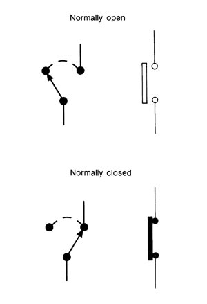
”. SWITCH POSITIONS
 Switches are shown in wiring diagrams as if the vehicle is in the “normal” condition.
A vehicle is in the “normal” condition when:
- ignition switch is “OFF”,
- doors, hood and trunk lid/back door are closed,
- pedals are not depressed, and
- parking brake is released.
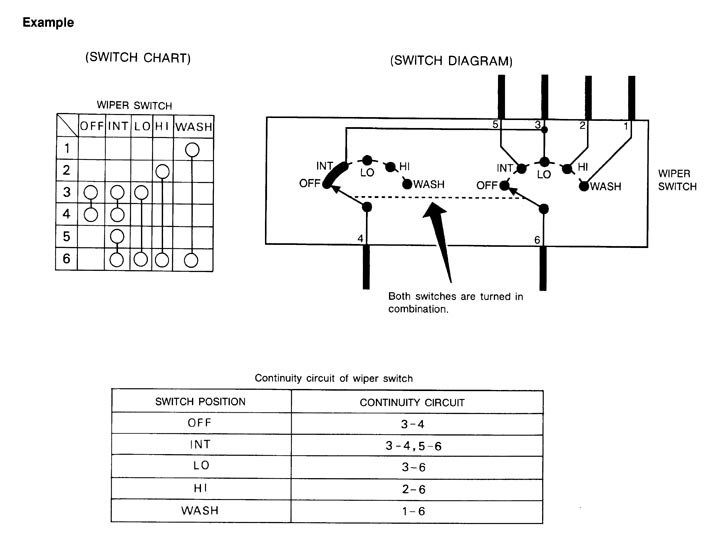
MULTIPLE SWITCHThe continuity of multiple switch is described in two ways as shown below.
- The switch chart is used in schematic diagrams.
- The switch diagram is used in wiring diagrams.