CONSULT-III/GST CHECKING SYSTEM
- Description
- CONSULT-III Function and System Application*1
- CONSULT-III/GST Data Link Connector (DLC) Circuit
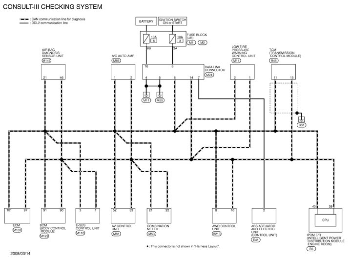
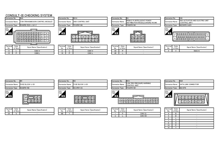
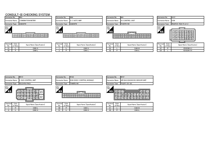
- Wiring Diagram - CONSULT-III/GST CHECKING SYSTEM -
Description
- When CONSULT-III/GST is connected with a data link connector (A) equipped on the vehicle side, it will communicate with the control unit equipped in the vehicle and then enable various kinds of diagnostic tests.
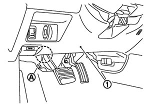
1 : Instrument driver lower panel - Refer to “CONSULT-III Software Operation Manual” for more information.
CONSULT-III Function and System Application*1
|
Diagnostic test mode |
Function |
ENGINE |
TRANSMISSION |
ALL MODE AWD/4WD |
VDC-R/TCS/ABS |
AIR BAG |
IPDM E/R |
BCM |
MULTI AV |
METER/M&A |
E-SUS |
AIR PRESSURE MONITOR |
HVAC |
|
Work Support |
This mode enables a technician to adjust some devices faster and more accurately. |
x |
x |
- |
x |
- |
- |
x |
- |
- |
- |
x |
x |
|
Self Diagnostic Results |
Retrieve DTC from ECU and display diagnostic items. |
x |
x |
x |
x |
x |
x |
x |
x |
x |
x |
x |
x |
|
Data Monitor |
Monitor the input/output signal of the control unit in real time. |
x |
x |
x |
x |
- |
x |
x |
x |
x |
x |
x |
x |
|
CAN Diagnosis |
This mode displays a network diagnosis result about CAN by a diagram. |
x |
x |
x |
x |
x |
x |
x |
x |
x |
x |
x |
x |
|
CAN Diagnosis Support Monitor |
It monitors the status of CAN communication. |
x |
x |
x |
x |
- |
x |
x |
x |
x |
x |
x |
x |
|
Active Test |
Send the drive signal from CONSULT-III to the actuator. The operation check can be performed. |
x |
x |
x |
x |
- |
x |
x |
- |
- |
x |
x |
x |
|
DTC & SRT confirmation |
The status of system monitoring tests and the self-diagnosis status/result can be confirmed. |
x |
- |
- |
- |
- |
- |
- |
- |
- |
- |
- |
- |
|
ECU Identification |
Display the ECU identification number (part number etc.) of the selected system. |
x |
x |
- |
- |
- |
x |
x |
x |
x |
x |
x |
x |
|
Function Test |
This mode can show results of self-diagnosis of ECU with either “OK” or “NG”. For engine, more practical tests regarding sensors/switches and/or actuators are available. |
x |
- |
- |
x |
x |
- |
x |
- |
- |
- |
- |
- |
|
Configuration |
Function to READ/WRITE vehicle configuration. |
- |
x |
- |
- |
- |
- |
x |
- |
- |
- |
- |
- |
|
Special Function |
Other results or histories, etc. that are recorded in ECU are displayed. |
- |
- |
- |
- |
x |
- |
- |
- |
x |
- |
- |
- |
CONSULT-III/GST Data Link Connector (DLC) Circuit
 INSPECTION PROCEDURE
If the CONSULT-III/GST cannot diagnose the system properly, check the following items.
| Symptom | Check item |
| CONSULT-III/GST cannot access any system. |
|
| CONSULT-III cannot access individual system. (Other systems can be accessed.) |
|
NOTE:
The DDL1 and DDL2 circuits from DLC pins 12, 13, 14 and 15 may be connected to more than one system. A short in a DDL circuit connected to a control unit in one system may affect CONSULT-III access to other systems.If the GST cannot operate properly, check the circuit based on the information of SAE J1962 and ISO 15031-3.
Wiring Diagram - CONSULT-III/GST CHECKING SYSTEM -