FRONT DRIVE SHAFT BOOT
Exploded View
 LEFT SIDE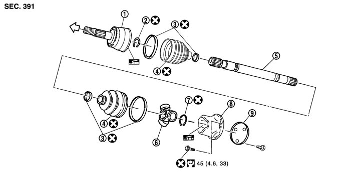
|
1. |
Joint sub-assembly |
2. |
Circular clip |
3. |
Boot band |
|
4. |
Boot |
5. |
Shaft |
6. |
Spider assembly |
|
7. |
Snap ring |
8. |
Housing |
9. |
Plug |
 : Wheel side : Wheel side |
|||||
 : NISSAN genuine grease or an equivalent. : NISSAN genuine grease or an equivalent. |
|||||
|
Refer to Components for symbols not described on the above. |
|||||
RIGHT SIDE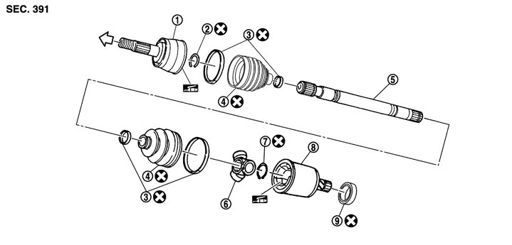
|
1. |
Joint sub-assembly |
2. |
Circular clip |
3. |
Boot band |
|
4. |
Boot |
5. |
Shaft |
6. |
Spider assembly |
|
7. |
Snap ring |
8. |
Housing |
9. |
Dust shield |
|
: Wheel side |
|||||
|
: NISSAN genuine grease or an equivalent. |
|||||
|
Refer to Components for symbols not described on the above. |
|||||
Inspection
INSPECTION AFTER REMOVAL- Move joint up/down, left/right, and in the axial directions. Check for motion that is not smooth and for significant looseness.
- Check boot for cracks, damage and leakage of grease.
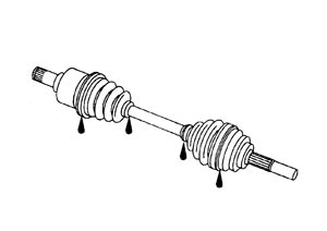
- Disassemble drive shaft and exchange malfunctioning part if there is a abnormal condition.
INSPECTION AFTER INSTALLATION- 1.Check wheel sensor harness for proper connection. Refer to Exploded View (GT-R certified NISSAN dealer).
- 2.Check the wheel alignment. Refer to Inspection.
- 3.Adjust neutral position of steering angle sensor. Refer to Special Repair Requirement (GT-R certified NISSAN dealer).