BODY ALIGNMENT
- Body Center Marks
- Description
- Underbody Projection Dimension
- Underbody Straight Line Dimension
- Engine Compartment
- Passenger Compartment
- Rear Body
Body Center Marks
A mark is placed on each part of the body to indicate the vehicle center. When repairing the vehicle frame (members, pillars, etc.) damaged by an accident which it enables more accurate and effective repair by using these marks together with body alignment specifications.
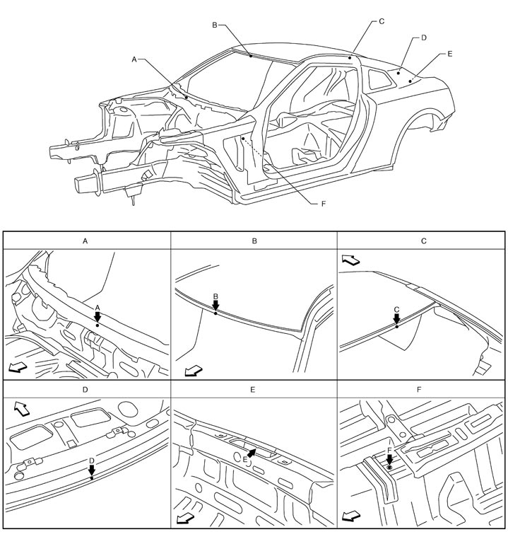
 | : Vehicle front |
| Points | Portion | Marks |
| A | Upper dash | Embossment |
| B | Front roof | Embossment |
| C | Rear roof | Embossment |
| D | Rear waist | Embossment |
| E | Rear panel | Flange end |
| F | Front floor center | Embossment |
Description
- All dimensions indicated in the figures are actual.
- When using a tracking gauge, adjust both pointers to equal length. Then check the pointers and gauge itself to make sure there is no free play.
- When a measuring tape is used, check that there is no elongation, twisting, or bending.
- Measurements should be taken at the center of the mounting holes.
- An asterisk (*) following the value at the measuring point indicates that the measuring point on the other side is symmetrically the same value.
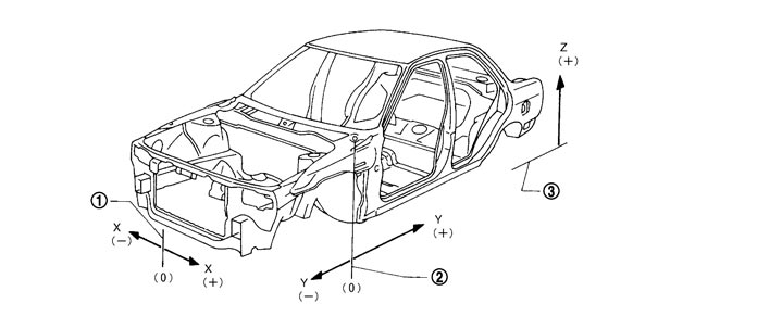
- The coordinates of the measurement points are the distances measured from the standard line of ″X″, ″Y″ and ″Z″.
- ″Z″: Imaginary base line [200 mm (7.87 in) below datum line (″0Z″ at design plan)]
|
1. |
Vehicle center |
2. |
Front axle center |
3. |
Imaginary base line |
Underbody Projection Dimension
 Measurement
Dimensions marked with ″*″ indicate symmetrically identical dimensions on both the right and left hand of the vehicle.
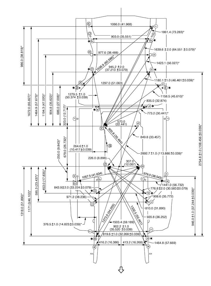
| Unit: mm (in) | |||||
| : Vehicle front | ||||
 | : Bolt head | ||||
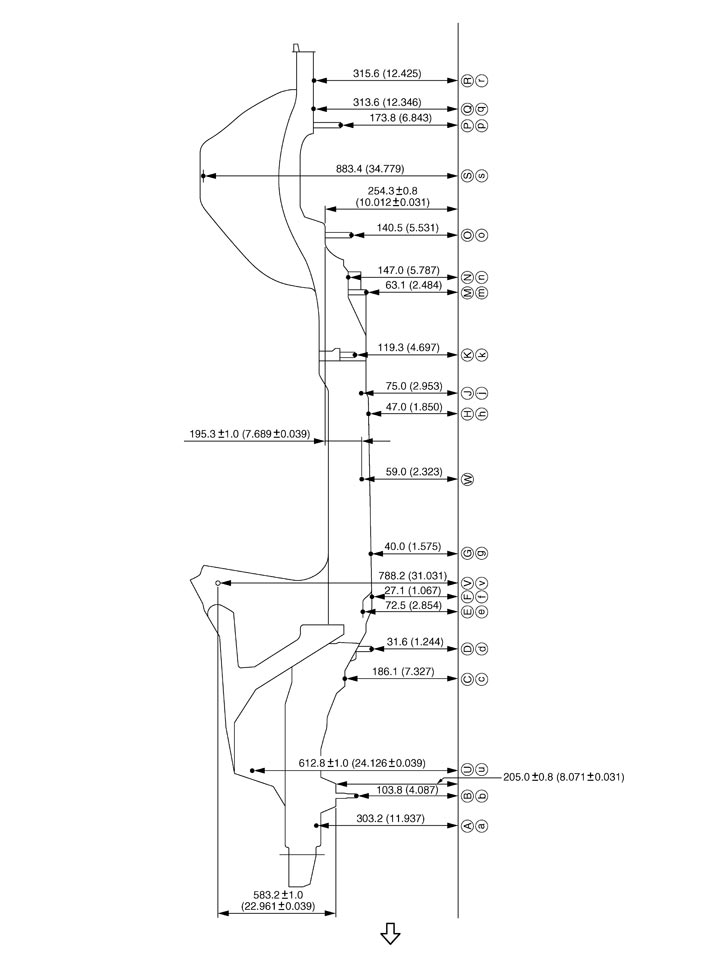
| Unit: mm (in) | |||||
| : Vehicle front | ||||
«Front and rear dimension not shown in the figure»
| Point | Dimension | Memo | Point | Dimension | Memo | Point | Dimension | Memo | ||||
| G - F | 231.0 (9.094)* | H - M | 638.5 (25.138)* | |||||||||
| H - J | 121.0 (4.764)* | H - Q | 1505.0 (59.252)* |
«Width dimension not shown in the figure»
| Point | Dimension | Memo | Point | Dimension | Memo | Point | Dimension | Memo | ||||
| F - f | 810.0 (31.890) | M - m | 1372.0 (54.016) | |||||||||
| J - j | 1445.2 (56.898) | Q - q | 1022.0 (40.236) |
«Opposite angle dimension not shown in the figure»
| Point | Dimension | Memo | Point | Dimension | Memo | Point | Dimension | Memo | ||||
| G - f | 672.0 (26.457) | H - j | 1014.8 (39.953)* | H - q | 1702.5 (67.027)* | |||||||
| g - F | 748.5 (29.468) | H - m | 1162.1 (45.752)* |
Measurement Points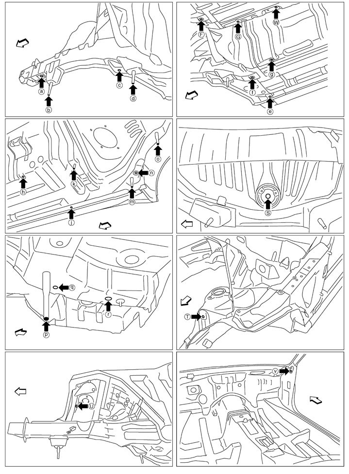
|
|
: Vehicle front |
|
|
|
|
| Point | Remarks | Point | Remarks |
| A, a, E, e | Front side member location hole center φ16 (0.63) | K, k | Transmission mounting installing bolt head |
| B, b, D, d | Front suspension member installing bolt head | M, m, O, o, P, p | Rear suspension member installing bolt head |
| C, c | Front side member measurement hole center φ14 (0.55) | R, r | Rear side member extension location hole center 18×16 (0.71×0.63) |
| F, f | Front side member extension location hole center φ16 (0.63) | S, s | Rear strut installing hole center φ30 (1.18) |
| G, g, H, h | Center front floor location hole center φ12 (0.47) | T, t, U, u | Front strut housing upper link installing hole center φ12.5 (0.492) |
| J, j | Inner sill measurement hole center φ9 (0.35) | V, v | Steering member installing hole center φ13 (0.51) |
| N, n, Q, q | Rear side member location hole center N, n: φ16 (0.63) Q, q: φ12 (0.47) | W | Tunnel stay mounting hole center φ14 (0.55) |
Underbody Straight Line Dimension
MeasurementDimensions marked with ″*″ indicate symmetrically identical dimensions on both the right and left hand of the vehicle.
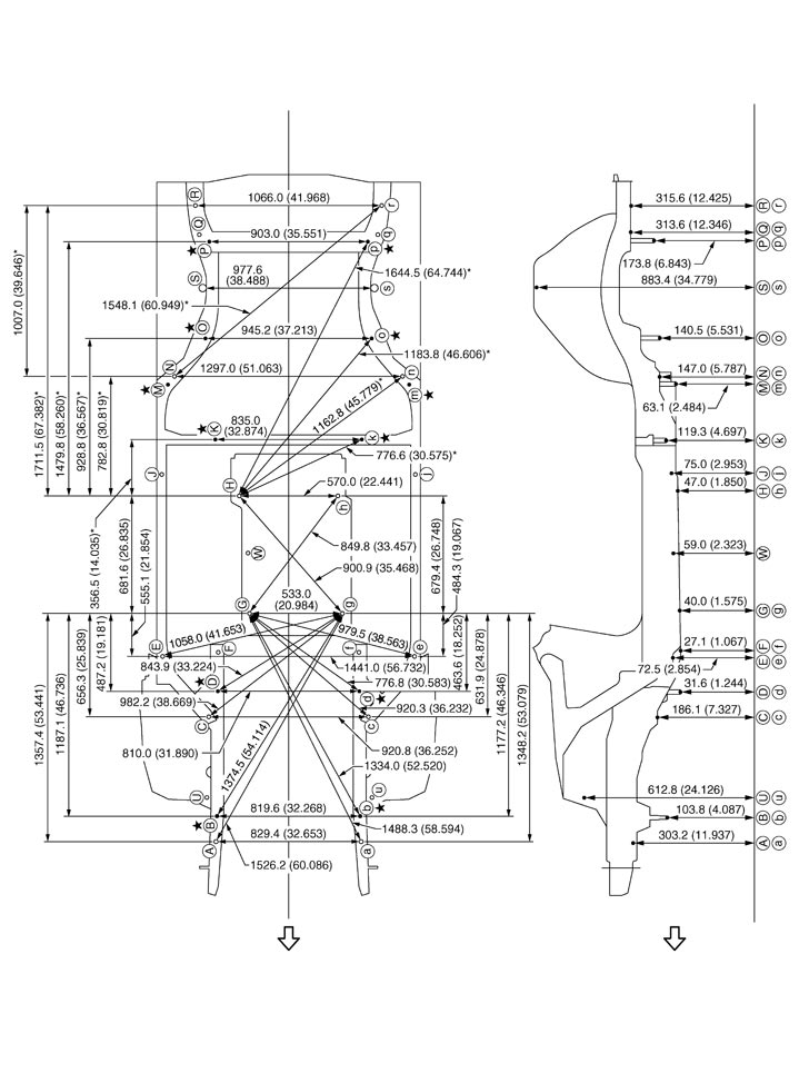
| Unit: mm (in) | |||||
| : Vehicle front | ||||
| : Bolt head | ||||
«Front and rear dimension not shown in the figure»
| Point | Dimension | Memo | Point | Dimension | Memo | Point | Dimension | Memo | ||||
| G - F | 292.5 (11.516) | H - J | 454.9 (17.909)* | H - Q | 1545.0 (60.827)* | |||||||
| g - f | 251.3 (9.894) | H - M | 754.2 (29.693)* |
«Width dimension not shown in the figure»
| Point | Dimension | Memo | Point | Dimension | Memo | Point | Dimension | Memo | ||||
| F - f | 810.0 (31.890) | M - m | 1372.0 (54.016) | |||||||||
| J - j | 1445.2 (56.898) | Q - q | 1022.0 (40.236) |
«Opposite angle dimension not shown in the figure»
| Point | Dimension | Memo | Point | Dimension | Memo | Point | Dimension | Memo | ||||
| G - f | 672.1 (26.461) | H - j | 1015.2 (39.968)* | H - q | 1723.3 (67.846)* | |||||||
| g - F | 748.6 (29.472) | H - m | 1162.2 (45.756)* |
Measurement Points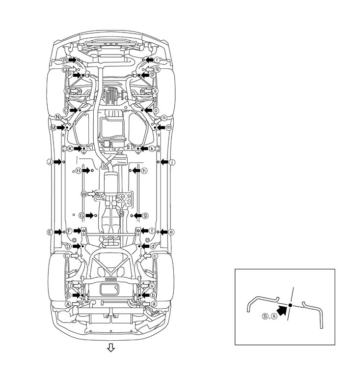
|
|
: Vehicle front |
|
|
|
|
| Points | Coordinates | Remarks | Points | Coordinates | Remarks | |||||
| X | Y | Z | X | Y | Z | |||||
| A | 416.2 (16.386) | −368.0 (−14.488) | 303.2 (11.937) | Hole φ16 (0.63) | K, k | ±417.5 (±16.437) | 1952.0 (76.850) | 119.3 (4.697) | Bolt head | |
| a | −413.2 (−16.268) | −368.0 (−14.488) | 303.2 (11.937) | Hole φ16 (0.63) | M, m | ±686.0 (±27.008) | 2267.5 (89.271) | 63.1 (2.484) | Bolt head | |
| B, b | ±409.8 (±16.134) | −221.0 (−8.701) | 103.8 (4.087) | Bolt head | N, n | ±648.5 (±25.531) | 2315.0 (91.142) | 147.0 (5.787) | Hole φ16 (0.63) | |
| C, c | ±460.4 (±18.126) | 354.7 (13.965) | 186.1 (7.327) | Hole φ14 (0.55) | O, o | ±472.6 (±18.606) | 2533.8 (99.756) | 140.5 (5.531) | Bolt head | |
| D, d | ±405.0 (±15.945) | 497.0 (19.567) | 31.6 (1.244) | Bolt head | P, p | ±451.5 (±17.776) | 3093.9 (121.807) | 173.8 (6.843) | Bolt head | |
| E, e | ±720.5 (±28.366) | 700.0 (27.559) | 72.5 (2.854) | Hole φ16 (0.63) | Q, q | ±511.0 (±20.118) | 3134.0 (123.386) | 313.6 (12.346) | Hole φ12 (0.47) | |
| F, f | ±405.0 (±15.945) | 719.0 (28.307) | 27.1 (1.067) | Hole φ16 (0.63) | R, r | ±533.0 (±20.984) | 3301.0 (129.960) | 315.6 (12.425) | Hole 18×16 (0.71×0.63) | |
| G | 226.0 (8.898) | 950.0 (37.402) | 40.0 (1.575) | Hole φ12 (0.47) | S, s | ±488.8 (±19.244) | 2823.3 (111.153) | 883.4 (34.779) | Hole φ30 (1.18) | |
| g | −307.0 (−12.087) | 950.0 (37.402) | 40.0 (1.575) | Hole φ12 (0.47) | U, u | ±451.1 (±17.760) | 172.7 (6.799) | 548.2 (21.583) | Hole φ12.5 (0.492) | |
| H, h | ±285.0 (±11.220) | 1629.0 (64.134) | 47.0 (1.850) | Hole φ12 (0.47) | W | 208.0 (8.189) | 1282.0 (50.472) | 59.0 (2.323) | Hole φ14 (0.55) | |
| J, j | ±722.6 (±28.449) | 1750.0 (68.898) | 75.0 (2.953) | Hole φ9 (0.35) | ||||||
Engine Compartment
MeasurementDimensions marked with ″*″ indicate symmetrically identical dimensions on both the right and left hand of the vehicle.
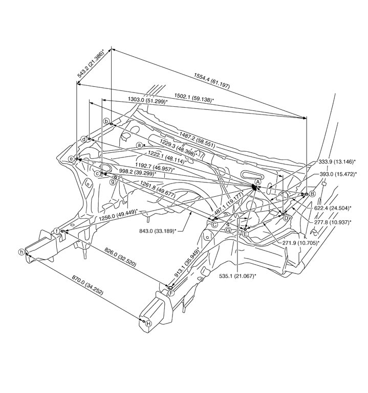
| Unit: mm (in) |
«The others»
| Point | Dimension | Memo | Point | Dimension | Memo | Point | Dimension | Memo | ||||
| G - g | 902.2 (35.520) |
Measurement Points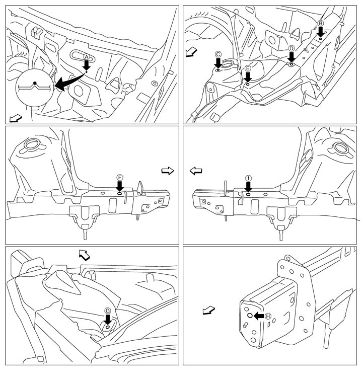
|
|
: Vehicle front |
|
|
|
|
| Point | Remarks | Point | Remarks |
| A, a | Upper dash positioning mark | E, e | Radiator core support mounting installing hole center φ14 (0.55) |
| B, b | Hood hinge installing hole center φ10 (0.39) | F, f | Front side member location hole center φ20 (0.79) |
| C, c | Front strut installing hole center φ8.5 (0.335) | G, g | Front strut housing upper link installing hole center φ12.5 (0.492) |
| D, d | Front fender installing hole center φ12 (0.47) | H, h | Bumper reinforcement mounting installing hole center φ10 (0.39) |
Passenger Compartment
MeasurementDimensions marked with ″*″ indicate symmetrically identical dimensions on both the right and left hand of the vehicle.
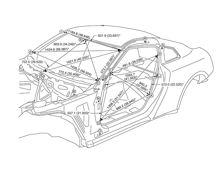
| Unit: mm (in) |
«The others»
| Point | Dimension | Memo | Point | Dimension | Memo | Point | Dimension | Memo | ||||
| E - e | 1424.4 (56.079) | H - h | 1373.4 (54.071) | M - P | 926.9 (36.492)* | |||||||
| E - g | 1560.4 (61.433)* | H - k | 1541.4 (60.685)* | N - J | 1198.1 (47.169)* | |||||||
| E - h | 1714.5 (67.500)* | J - S | 411.0±0.7 (16.181±0.028)* | N - K | 1084.5 (42.697)* | |||||||
| E - k | 1734.6 (68.291)* | K - k | 1491.6 (58.724) | N - Q | 268.5±1.0 (10.571±0.039)* | |||||||
| F - f | 1486.0 (58.504) | M - E | 923.5 (36.358)* | N - R | 1222.4±1.0 (48.126±0.039)* | |||||||
| F - j | 1827.8 (71.960)* | M - F | 883.7±1.0 (34.791±0.039)* | N - S | 1404.3±1.0 (55.287±0.039)* | |||||||
| G - g | 1491.6 (58.724) | M - G | 758.7±1.0 (29.870±0.039)* | O - J | 1269.2 (49.968)* | |||||||
| G - h | 1939.8 (76.370)* | M - H | 1405.6±1.0 (55.338±0.039)* | O - K | 1065.1 (41.933)* | |||||||
| G - k | 1789.8 (70.464)* | M - K | 1144.6±1.0 (45.063±0.039)* | P - p | 1572.6±1.5 (61.916±0.059) |
Measurement Points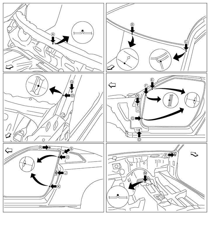
|
|
: Vehicle front |
|
|
|
|
| Point | Remarks | Point | Remarks |
| A | Upper dash positioning mark of center positioning mark | M | Front floor positioning mark of center positioning mark |
| B | Roof flange end of center positioning mark | N, n, O, o | Door hinge installing hole center N, n: φ12.2 (0.480) O, o: φ14 (0.55) |
| C, c, F, f | Front pillar joggle | P, p | Steering member installing hole center φ13 (0.51) |
| D, d, E, e, G, g | Front pillar indent | Q, q, R, r | Front pillar finisher installing hole center 12×8 (0.47×0.31) |
| H, h, K, k | Rear fender indent | S, s | Side window installing hole center 9×7 (0.35×0.28) |
| J, j | Door catcher installing hole center φ28 (1.10) |
Rear Body
MeasurementDimensions marked with ″*″ indicate symmetrically identical dimensions on both the right and left hand of the vehicle.
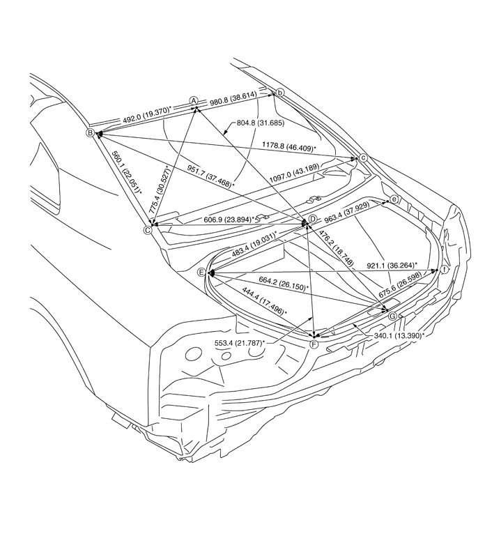
| Unit: mm (in) |
Measurement Points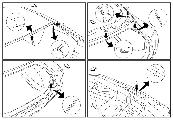
|
|
: Vehicle front |
|
|
|
|
|
Point |
Remarks |
Point |
Remarks |
|
A |
Roof flange end of center positioning mark |
E, e |
Rear fender corner joggle |
|
B, b, C, c |
Rear fender joggle |
F, f |
Rear fender brace joggle |
|
D |
Rear waist flange end of center positioning mark |
G |
Rear panel lock installing hole corner section of center positioning mark |