BODY CONSTRUCTION
Body Construction
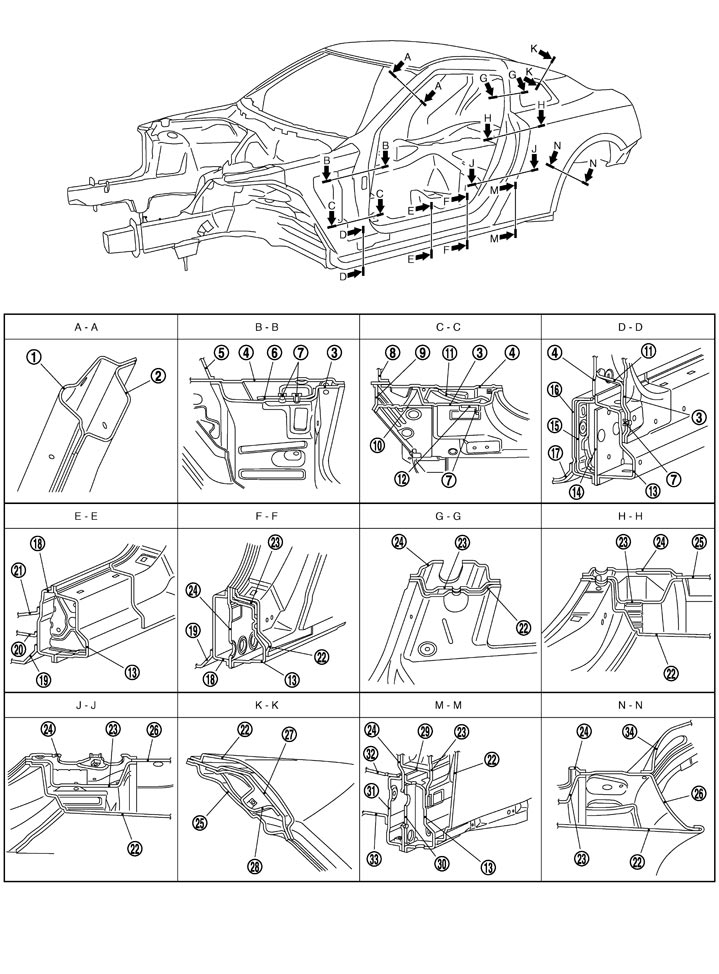
|
1. |
Outer front pillar |
2. |
Inner upper front pillar |
3. |
Front pillar hinge brace |
|
4. |
Upper rear hoodledge |
5. |
Upper dash |
6. |
Upper hinge plate |
|
7. |
Weld nut |
8. |
Lower dash upper |
9. |
Hoodledge extension |
|
10. |
Hoodledge reinforcement gusset |
11. |
Lower front pillar gusset |
12. |
Cowl top extension bracket |
|
13. |
Outer sill reinforcement |
14. |
Outer sill brace |
15. |
Inner sill reinforcement front |
|
16. |
Front side member |
17. |
Lower dash |
18. |
Inner sill |
|
19. |
Front floor |
20. |
2nd crossmember |
21. |
Outer front seat mounting bracket |
|
22. |
Rear fender |
23. |
Lock pillar reinforcement |
24. |
Inner lock pillar |
|
25. |
Inner rear pillar |
26. |
Outer rear wheelhouse |
27. |
Outer rear pillar |
|
28. |
Rear pillar gusset |
29. |
Lower lock pillar reinforcement |
30. |
Outer sill brace |
|
31. |
Inner sill extension |
32. |
Rear seat crossmember reinforcement |
33. |
Rear seat crossmember |
|
34. |
Inner rear wheelhouse |
|
|
|
|
Fusible Insulator Applying Part
Apply the fusible insulator (melsheet) to the floor upper surface and dashboard panel interior side to block noise, vibration, and exhaust gas heat.
Use the fusible insulators (A) - (D) for the front floor set as the service parts. Place these parts in the positions shown in the figure, heat these parts by halogen heaters, etc., and then fix the fusible insulators to the floor.
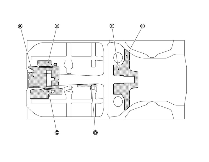
| A. | T=2.0 mm (0.08 in) | B. | T=2.0 mm (0.08 in) | C. | T=2.0 mm (0.08 in) |
| D. | T=2.0 mm (0.08 in) | E. | T=3.0 mm (0.12 in) | F. | T = 3.0 mm (0.12 in) LH and RH are symmetrical. |
 : Fusible insulator applying part : Fusible insulator applying part | |||||
■ CAUTION ■
Select the fusible insulators (E) and (F) used for the rear floor panel from among the commercial service tool shown in the following table, and then cut and paste them. | Part number | Size |
| G5930-89904 | 500 × 1000 × 1.5T (19.69 × 39.37 × 0.059T) |
| G5930-89905 | 500 × 1000 × 3.0T (19.69 × 39.37 × 0.118T) |
| G5930-89906 | 500 × 1000 × 6.0T (19.69 × 39.37 × 0.236T) |
Rear Fender Hemming Process
- A wheel arch is to be installed and hemmed over the left and right outer wheel houses.
- In order to hem the wheel arch, it is necessary to repair any damaged or defaced parts around outer wheel house.
■ CAUTION ■
Ensure that the area that is to be glued around the outer wheelhouse is undamaged or defaced.
 PROCEDURE OF THE HEMMING PROCESS
- Peel off old bonding material on the surface of the outer wheelhouse and clean thoroughly.
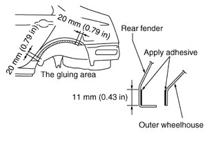
- Peel off a primer coat in the specified area where new adhesive is to be applied on rear fender (the replacing part).
- Apply new adhesive to both specified areas of the outer wheelhouse and rear fender.
|
<Adhesive> |
3M™ Automix™ Panel Bonding Adhesive 08115 or equivalent |
- Attach rear fender to the body of the car, and weld the required part except the hemming part.
- Bend the welded part starting from the center of the wheel arch gradually with a hammer and a dolly. (Also hem the end of the flange.)
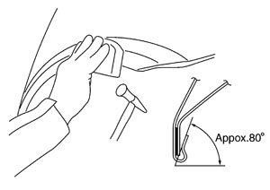
- Hemming with a hammer is conducted to an approximate angle of 80 degrees.
- Starting from the center, hem the wheel arch gradually, using slight back and forth motion with a hemming tool.
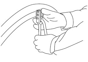
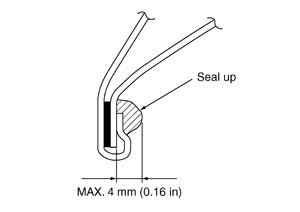
- Seal up the area around the hemmed end of the flange.