WHEEL ALIGNMENT
Inspection
 DESCRIPTION
■ CAUTION ■
- Kingpin inclination angles cannot be adjusted.
- If kingpin inclination angle is outside the standard, check front suspension parts for wear and damage. Replace suspect parts if a malfunction is detected.
- Kingpin inclination angle is reference value, no inspection is required.
- Measure wheel alignment under unladen conditions.
NOTE:
“Unladen conditions” means that fuel, engine coolant, and lubricant are full. Jack, hand tools and mats are in designated positions.
PRELIMINARY CHECKCheck the following:
- Tires for improper air pressure and wear.
- Wheel bearing axial end play. Refer to Inspection.
- Transverse link or upper link ball joint axial end play. Refer to Inspection (GT-R certified NISSAN dealer).
- Shock absorber operation.
- Each mounting part of axle and suspension for looseness and deformation.
- Each of front suspension member, shock absorber, upper link and transverse link for cracks, deformation and other damage.
- Vehicle height (posture).
GENERAL INFORMATION AND RECOMMENDATIONS- A four-wheel thrust alignment should be performed.
- This type of alignment is recommended for any NISSAN/INFINITI vehicle.
- The four-wheel “thrust” process helps ensure that the vehicle is properly aligned and the steering wheel is centered.
- The alignment rack itself should be capable of accepting any NISSAN/INFINITI vehicle.
- The rack should be checked to ensure that it is level.
- Make sure the machine is properly calibrated.
- Your alignment equipment should be regularly calibrated in order to give correct information.
- Check with the manufacturer of your specific equipment for their recommended Service/Calibration Schedule.
ALIGNMENT PROCESSIMPORTANT:
Use only the alignment specifications listed in this Service Manual.
- When displaying the alignment settings, many alignment machines use “indicators” : (Green/red, plus or minus, Go/No Go). Do not use these indicators.
- The alignment specifications programmed into your machine that operate these indicators may not be correct.
- This may result in an ERROR.
Adjustment
TOE-INLoosen the steering outer socket, and then adjust the length using steering inner socket.
| Standard | |
| Toe-in | : Refer to Wheel Alignment. |
■ CAUTION ■
- Always evenly adjust both toe-in alternately and adjust the difference between the left and right to the standard.
- Always fix the steering inner socket when tightening the steering outer socket.
CAMBERLoosen the mounting nut of transverse link (1) and front suspension member, and then adjust using adjust bolt (2).
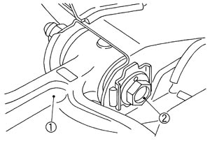
| Standard | |
| Camber | : Refer to Wheel Alignment. |
■ CAUTION ■
Always hold the adjust bolt firmly when tightening nut. CASTERRemove the upper link mounting bolts (body side), and then adjust them using the thickness (increasing and decreasing) of shims (A).
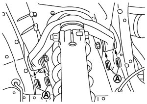
| Standard | |
| Caster | : Refer to Wheel Alignment. |
■ CAUTION ■
- Refer to figure for selection of shim.
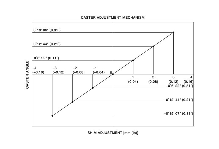
- Assemble the shims and the rubber bushings while facing the rubber bushings toward the upper link side.
NOTE:
The shims and rubber bushings are fitted on a new vehicle [shim: 3 mm (0.12 in)] are a single unit. However the shims for adjustment and rubber bushings are separated parts. When shim: 6 mm (0.24in) is selected, fix it on one side only.