WHEEL ALIGNMENT
Inspection
 DESCRIPTION
Measure wheel alignment under unladen conditions.
NOTE:
“Unladen conditions” means that fuel, engine coolant, and lubricant are full. Jack, hand tools and mats are in designated positions. PRELIMINARY CHECKCheck the following:
- Tires for improper air pressure and wear.
- Wheel bearing axial end play. Refer to Inspection.
- Ball joint axial end play of suspension arm. Refer to Inspection (GT-R certified NISSAN dealer).
- Shock absorber operation.
- Each mounting point of axle and suspension for looseness and deformation.
- Each of front lower link, rear lower link, radius rod, rear suspension member, suspension arm and shock absorber for cracks, deformation, and other damage.
- Vehicle height (posture).
GENERAL INFORMATION AND RECOMMENDATIONS- A four-wheel thrust alignment should be performed.
- This type of alignment is recommended for any NISSAN/INFINITI vehicle.
- The four-wheel “thrust” process helps ensure that the vehicle is properly aligned and the steering wheel is centered.
- The alignment rack itself should be capable of accepting any NISSAN/INFINITI vehicle.
- The rack should be checked to ensure that it is level.
- Make sure the machine is properly calibrated.
- Your alignment equipment should be regularly calibrated in order to give correct information.
- Check with the manufacturer of your specific equipment for their recommended Service/Calibration Schedule.
ALIGNMENT PROCESSIMPORTANT:
Use only the alignment specifications listed in this Service Manual.
- When displaying the alignment settings, many alignment machines use “indicators”: (Green/red, plus or minus, Go/No Go). Do not use these indicators.
- The alignment specifications programmed into your machine that operate these indicators may not be correct.
- This may result in an ERROR.
Adjustment
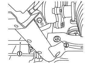
TOE-IN- 1.Remove rear diffuser. Refer to Exploded View.
- 2.Adjust using the adjust bolt (2) of rear lower link (1).
- Always evenly adjust both toe-in alternately and adjust the difference between the left and right to the standard.
- Always hold the adjust bolt firmly when tightening nut.
| Standard | |
| Toe-in | : Refer to Wheel Alignment. |
■ CAUTION ■
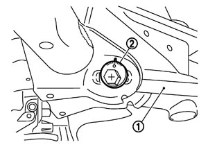
CAMBER- 1.Remove rear diffuser. Refer to Exploded View.
- 2.Adjust using the adjust bolt (2) of front lower link (1).
- Always hold the adjust bolt firmly when tightening nut.
- Always check toe-in after adjusting camber.
| Standard | |
| Camber | : Refer to Wheel Alignment. |
■ CAUTION ■