AV CONTROL UNIT
BASE AUDIO WITH NAVIGATION
Reference Value
 VALUES ON THE DIAGNOSIS TOOL
CONSULT-III MONITOR ITEM
|
Monitor Item |
Condition |
Value/Status | |
| VHCL SPD SIG | Ignition switch ON | Vehicle speed > 0 km/h (0 MPH) | On |
| Vehicle speed = 0 km/h (0 MPH) | Off | ||
| PKB SIG | Ignition switch ON | Parking brake is applied. | On |
| Parking brake is released. | Off | ||
| ILLUM SIG | Ignition switch ON | Light switch ON | On |
| Light switch OFF | Off | ||
| IGN SIG | Ignition switch ON | — | On |
| Ignition switch ACC | — | Off | |
| REV SIG | Ignition switch ON | Selector lever in R position | On |
| Selector lever in any position other than R | Off |
TERMINAL LAYOUT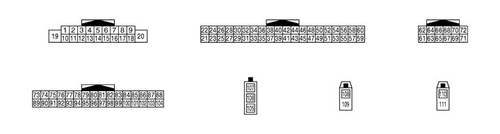 PHYSICAL VALUES
|
Terminal (Wire color) |
Description |
Condition |
Reference value (Approx.) |
|||
|
+ |
– |
Signal name |
Input/Output |
|||
|
1 (V) |
Ground |
Audio amp. ON signal |
Output |
Ignition switch ON |
— |
11 V |
|
2 (R) |
3 (G) |
Sound signal front LH |
Output |
Ignition switch ON |
Voice output |
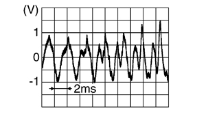
|
|
4 (B) |
5 (W) |
Sound signal rear LH |
Output |
Ignition switch ON |
Voice output |
|
|
6 (V) |
15 (GR) |
Steering switch signal A |
Input |
Ignition switch ON |
Keep pressing SOURCE switch. |
0 V |
Keep pressing SEEK switch to  . . |
1 V |
|||||
Keep pressing SEEK switch to  . . |
2 V |
|||||
Keep pressing  switch. switch. |
3 V |
|||||
|
Keep pressing START / STOP switch. |
4 V |
|||||
|
Except for above. |
5 V |
|||||
|
7 (V) |
Ground |
ACC power supply |
Input |
Ignition switch ACC |
— |
Battery voltage |
|
9 (R) |
Ground |
Illumination signal |
Input |
OFF |
Lighting switch is OFF. |
0 V |
|
Lighting switch is ON. |
12 V |
|||||
|
10 (BR) |
— |
Shield |
— |
— |
— |
— |
|
11 (R) |
12 (L) |
Sound signal front RH |
Output |
Ignition switch ON |
Voice output |
|
|
13 (B) |
14 (Y) |
Sound signal rear RH |
Output |
Ignition switch ON |
Voice output |
|
|
15 (GR) |
Ground |
Steering switch signal GND |
— |
Ignition switch ON |
— |
0 V |
|
16 (SB) |
15 (GR) |
Steering switch signal B |
Input |
Ignition switch ON |
Keep pressing VOL switch to -. |
0 V |
|
Keep pressing VOL switch to +. |
1 V |
|||||
Keep pressing  switch. switch. |
2 V |
|||||
|
Keep pressing MRK switch. |
3 V |
|||||
|
Except for above. |
5 V |
|||||
|
19 (Y) |
Ground |
Battery power supply |
Input |
Ignition switch OFF |
— |
Battery voltage |
|
21 (B) |
Ground |
GND |
— |
Ignition switch ON |
— |
0 V |
|
22 (Y) |
Ground |
Battery power supply |
Input |
Ignition switch OFF |
— |
Battery voltage |
|
23 (B) |
Ground |
GND |
— |
Ignition switch ON |
— |
0 V |
|
24 (Y) |
Ground |
Battery power supply |
Input |
Ignition switch OFF |
— |
Battery voltage |
|
25 (V) |
Ground |
ACC power supply |
Input |
Ignition switch ACC |
— |
Battery voltage |
|
26 (L) |
27 |
Microphone VCC |
Output |
Ignition switch ON |
— |
5 V |
|
27 |
Ground |
Shield (Microphone ground) |
— |
Ignition switch ON |
— |
0 V |
|
28 (P) |
27 |
Microphone signal |
Input |
Ignition switch ON |
Give a voice |
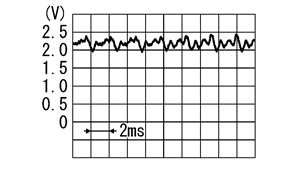
|
|
35 (W) |
Ground |
Ignition signal |
Input |
Ignition switch ON |
— |
Battery voltage |
|
36 (R) |
Ground |
Parking brake signal |
Input |
Ignition switch ON |
Parking brake ON |
0 V |
|
Parking brake OFF |
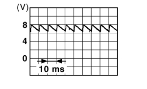
|
|||||
|
37 (O) |
Ground |
Reverse signal |
Input |
Ignition switch ON |
R position |
12 V |
|
Other than R position |
0 V |
|||||
|
38 (V) |
Ground |
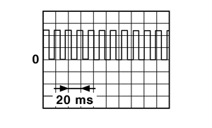
Vehicle speed signal (8‐pulse) |
Input |
Ignition switch ON |
When vehicle speed is approx. 40 km/h (25MPH) |
NOTE:
The maximum voltage varies depending on the specification (connected units).
|
|
43 (B) |
Ground |
GND |
— |
Ignition switch ON |
— |
0 V |
|
48 (G) |
— |
AV communication signal (H) |
Input/Output |
— |
— |
— |
|
49 (R) |
— |
AV communication signal (L) |
Input/Output |
— |
— |
— |
|
50 (G) |
— |
AV communication signal (H) |
Input/Output |
— |
— |
— |
|
51 (R) |
— |
AV communication signal (L) |
Input/Output |
— |
— |
— |
|
52 (L) |
— |
CAN–H |
Input/Output |
— |
— |
— |
|
53 (P) |
— |
CAN–L |
Input/Output |
— |
— |
— |
|
61 (R) |
Ground |
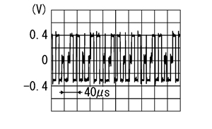
RGB signal (R: red) |
Output |
Ignition switch ON |
Start confirmation/adjustment mode, and then display color bar by selecting “Color Spectrum Bar” on DISPLAY DIAGNOSIS screen. |
|
|
62 (G) |
Ground |
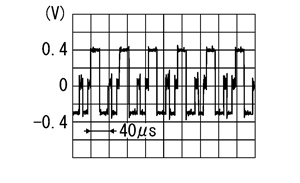
RGB signal (G: green) |
Output |
Ignition switch ON |
Start confirmation/adjustment mode, and then display color bar by selecting “Color Spectrum Bar” on DISPLAY DIAGNOSIS screen. |
|
|
63 (B) |
Ground |
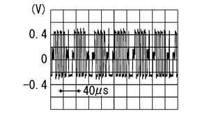
RGB signal (B: blue) |
Output |
Ignition switch ON |
Start confirmation/adjustment mode, and then display color bar by selecting “Color Spectrum Bar” on DISPLAY DIAGNOSIS screen. |
|
|
64 |
— |
Shield |
— |
— |
— |
— |
|
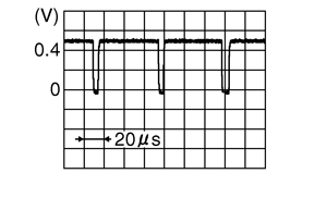
65 (W) |
Ground |
RGB synchronizing signal |
Output |
Ignition switch ON |
— |
|
|
66 |
— |
Shield |
— |
— |
— |
— |
|
67 (W) |
Ground |
RGB area (YS) signal |
Output |
Ignition switch ON |
At RGB image displayed |
5 V |
|
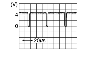
68 (R) |
Ground |
Horizontal synchronizing (HP) signal |
Input |
Ignition switch ON |
— |
|
|
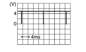
69 (B) |
Ground |
Vertical synchronizing (VP) signal |
Input |
Ignition switch ON |
— |
|
|
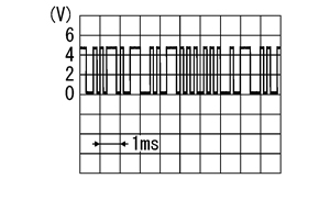
70 (BR) |
Ground |
Communication signal (CONT→DISP) |
Output |
Ignition switch ON |
When adjusting display brightness. |
|
|
71 (Y) |
Ground |
Communication signal (DISP→CONT) |
Input |
Ignition switch ON |
When adjusting display brightness. |
|
|
72 |
— |
Shield |
— |
— |
— |
— |
|
85 (SB) |
Ground |
Disk eject signal |
Input |
— |
Pressing the disk eject switch |
0 V |
|
Except for above |
5 V |
|||||
|
86 |
— |
Shield |
— |
— |
— |
— |
|
102 (BR) |
Ground |
Switch GND |
— |
Ignition switch ON |
— |
0 V |
|
105 |
— |
FM sub |
Input |
— |
— |
— |
|
106 |
— |
AM–FM main |
Input |
— |
— |
— |
|
107 |
Ground |
Antenna amp. ON signal |
Output |
Ignition switch ON |
— |
12 V |
|
108 |
Ground |
Satellite antenna signal |
Input |
Ignition switch ON |
Not connected to satellite antenna connector |
5 V |
|
109 |
— |
Shield |
— |
— |
— |
— |
|
110 |
Ground |
GPS antenna signal |
Input |
Ignition switch ON |
Not connected to GPS antenna connector |
5 V |
|
111 |
— |
Shield |
— |
— |
— |
— |
Wiring Diagram - BASE AUDIO WITH NAVIGATION SYSTEM -
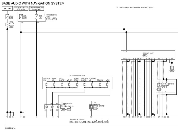
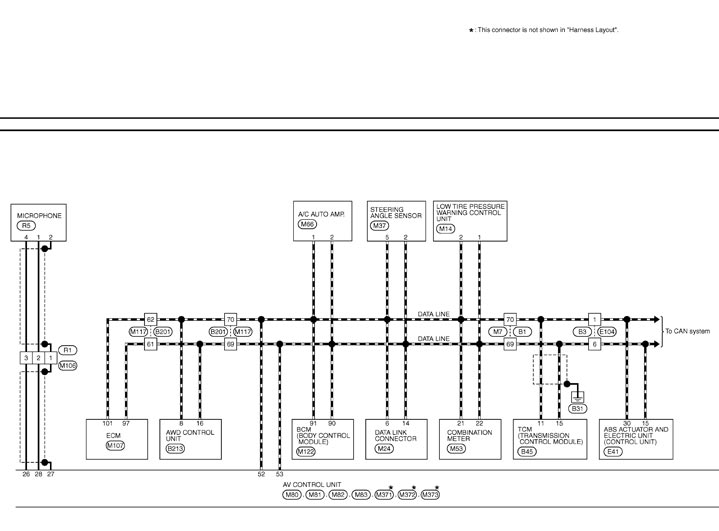
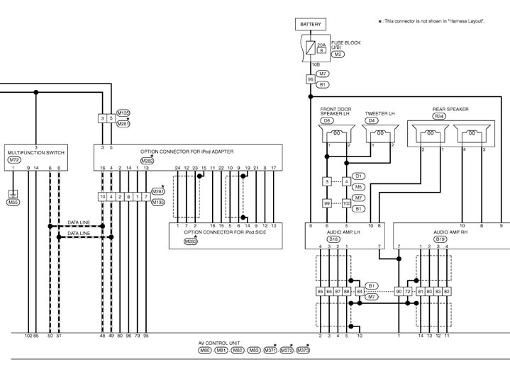
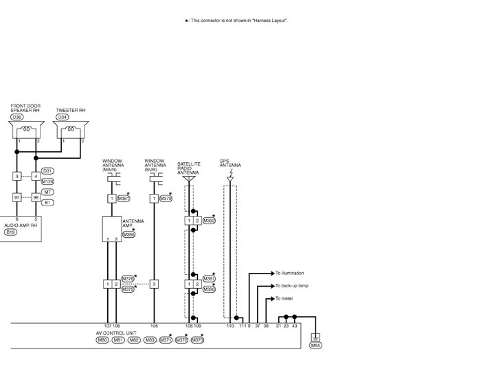
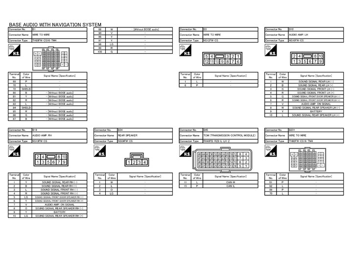
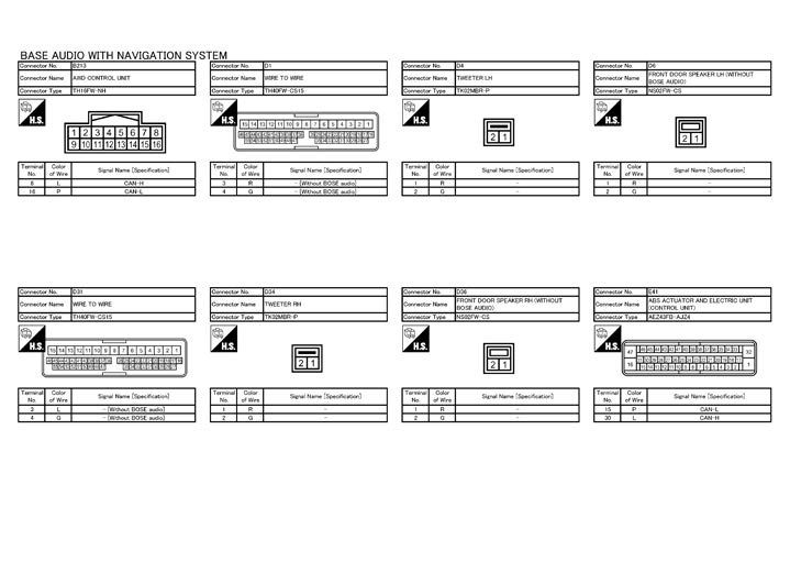
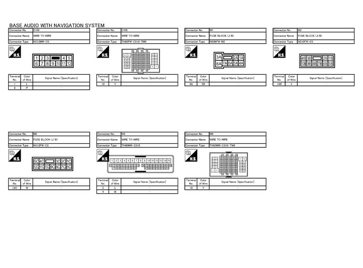
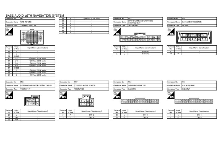
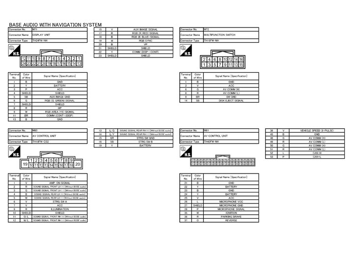
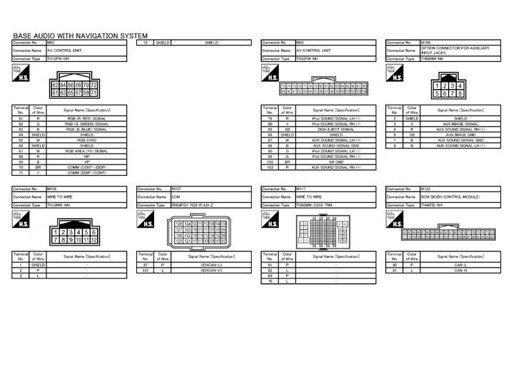
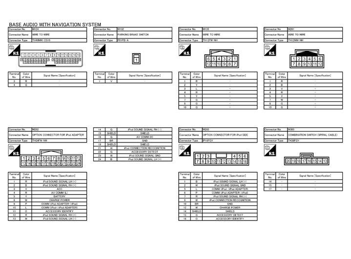
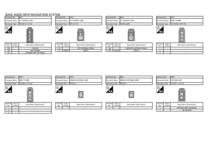
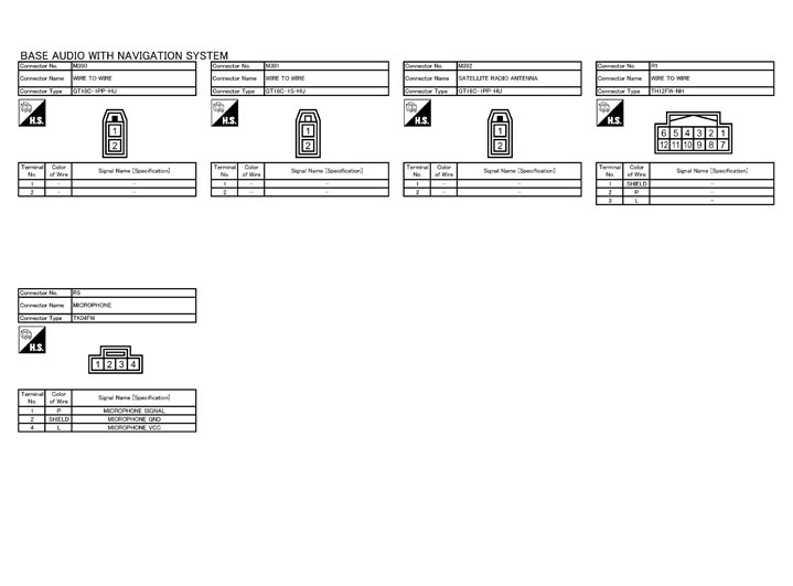
NOTE:
The name MULTIFUNCTION SWITCH indicates the integration of PRESET SWITCH and MULTIFUNCTION SWITCH virtually.
Fail-Safe
When the ambiance temperature becomes extremely low or extremely high, or when HDD is malfunctioning, AV control unit displays the message and limits the AV control unit function.
FAIL‐SAFE CONDITIONS- When the ambiance temperature is −20°C (−4°F) or less, or when it is 70°C (158°F) or more
- when HDD is malfunctioning
 Display
The messages displayed on fail-safe conditions are as shown below:
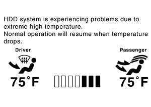
| Fail-safe mode | Display indication (fail-safe status display) |
| HDD at low temperature | The HDD does not operate when at a low temperature, and some functions cannot be used. These may return if the temperature increases |
| HDD at high temperature | The HDD does not operate when at a high temperature, and some functions cannot be used. These may return if the temperature decreases |
| When HDD is malfunctioning | A malfunction is detected on the HDD. Contact the dealer |
DESCRIPTION OF CONTROLS| Function | When Fail‐safe Function is activated | |
| Air conditioner | Operation | Only the operation of preset switch is possible. |
| Display |
| |
| Audio | Operation | Only ON/OFF of the audio system by preset switch and volume operation are possible. |
| Display | No display (“Fail-safe mode” is displayed). | |
| Hands-free phone | Operation | It cannot be operated. |
| Navigation | Operation | It cannot be operated. |
| Multifunction meter | Operation | It cannot be operated. |
| Self diagnosis | The display indication is a simple indication of the fail-safe condition. | |
| CONSULT-III diagnosis | It cannot be diagnosed. | |
Ability Operation Mode There is an ability operation mode for Fail‐safes due to low or high ambiance temperature.
If HDD data can be read, fail‐safe is shown, then normal displays are displayed only for functions which can be operated.
RELEASE CONDITIONS OF FAIL‐SAFE Fail‐safe is released on following conditions and normal mode is restored.
When the temperature of HDD is low or highIf the ambient temperature becomes out of fail-safe condition range, normal mode is restored.
When HDD is malfunctioningIf the malfunction disappears, normal mode is restored.
NOTE:
- If fail‐safe mode due to HDD malfunction is seen continuously, replace AV control unit.
- If fail‐safe mode due to HDD malfunction is seen temporarily, check the “Error History” of Confirmation/Adjustment mode. If this is normal, then continue the normal operation, observing the function. (It might be a temporary malfunction of HDD.)
DTC Index
SELF-DIAGNOSIS RESULTS DISPLAY ITEM|
DTC |
Display item |
Refer to |
|
U1000 |
CAN COMM CIRCUIT [U1000] |
Diagnosis Procedure
|
|
U1010 |
CONTROL UNIT (CAN) [1010] |
Diagnosis Procedure
|
|
U1310 |
CONTROL UNIT (AV) [U1310] |
DTC Logic
|
|
U1200 |
Control Unit FLASH‐ROM [1200] |
DTC Logic
|
|
U1201 |
Gyro NO CONN [1201] |
DTC Logic
|
|
U1202 |
G-SENSOR NO CONN [U1202] |
DTC Logic
|
|
U1216 |
CAN CONT [U1216] |
DTC Logic
|
|
U1217 |
BLUETOOTH CONN [U1217] |
DTC Logic
|
|
U1218 |
HDD CONN [U1218] |
DTC Logic
|
|
U1219 |
HDD READ [U1219] |
DTC Logic
|
|
U1220 |
XM SERIAL COMM [U1220] |
Diagnosis Procedure
|
|
U121A |
HDD WRITE [U121A] |
DTC Logic
|
|
U121B |
HDD COMM [U121B] |
DTC Logic
|
|
U121C |
HDD ACCESS [U121C] |
DTC Logic
|
|
U121D |
DSP CONN [U121D] |
DTC Logic
|
|
U121E |
DSP COMM [U121E] |
DTC Logic
|
|
U121F |
INTERNAL COMM [U121F] |
DTC Logic
|
|
U1204 |
GPS COMM [U1204] |
DTC Logic
|
|
U1205 |
GPS ROM [U1205] |
DTC Logic
|
|
U1206 |
GPS RAM [U1206] |
DTC Logic
|
|
U1207 |
GPS RTC [U1207] |
DTC Logic
|
|
U1243 |
FRONT DISP CONN [U1243] |
DTC Logic
|
|
U1244 |
GPS ANTENNA CONN [U1244] |
DTC Logic
|
|
U1258 |
XM ANTENNA CONN [U1258] |
DTC Logic
|
|
U1300 U121F |
|
Description
|
|
U1300 U1240 |
|
Description
|