POWER DISTRIBUTION SYSTEM
POWER DISTRIBUTION SYSTEM
System Description
- PDS (POWER DISTRIBUTION SYSTEM) is the system that BCM controls with the operation of the push-button ignition switch and performs the power distribution to each power circuit. This system is used instead of the mechanical power supply changing mechanism with the operation of the conventional key cylinder.
- The push-button ignition switch can be operated when Intelligent Key is in the following condition. Refer to Engine Start Function for details.
- Intelligent Key is in the detection area of the inside key antenna
- Insert Intelligent Key into the key slot
- Insert key fob into the key slot
- The push-button ignition switch operation is input to BCM as a signal. BCM changes the power supply position according to the status and operates the following relays to supply power to each power circuit.
- Ignition relay (built into IPDM E/R)
- Ignition relay (inserted into fuse block)
- ACC relay
- Blower relayNOTE:The engine switch operation changes due to the conditions of brake pedal, shift lever position and vehicle speed.
- The power supply position can be confirmed with the illuminating of the indicators around the push-button ignition switch.
 BATTERY SAVER SYSTEM
When all of the following conditions are met for 60 minutes, the battery saver system will cut off the power supply to prevent battery discharge.
- The ignition switch is in the ACC position
- All doors are closed
- Shift lever is in the P position
 Reset Condition of Battery Saver System
In order to prevent the battery from discharging, the battery saver system will cut off the power supply when all doors are closed, the selector lever is in the P position and the ignition switch is left in the ACC position for 60 minutes. If any of the following conditions are met the battery saver system is released and the steering will change automatically to the LOCK position from the OFF position.
- Opening any door
- Operating with door key cylinder on door lock
- Operating with request switch on door lock
- Operating with Intelligent Key on door lock
STEERING LOCK OPERATIONSteering is locked by steering lock unit when ignition switch is in the OFF position, selector shift is in the P position and any of the following conditions are met.
- Opening door
- Closing door
- Door is locked with request switch
- Door is locked with Intelligent Key
PUSH-BUTTON IGNITION SWITCH OPERATION PROCEDUREThe power supply position changing operation can be performed with the following operations.
Operation Enable Condition- When an Intelligent Key is within the detection area of inside key antenna and when it is inserted into the key slot, the operation is as per the following.
- When starting the engine, the BCM monitors the following engine start conditions,
- Brake pedal operating condition
- Shift lever position
- Vehicle speed
- Unless each start condition is fulfilled, the engine will not respond regardless of how many times the engine switch is pressed. At that time, illumination repeats the position in the order of LOCK→ACC→ON→OFF.
Operation Condition| Power supply position | Engine start/stop condition | Push-button ignition switch operation frequency | |
| Brake pedal | Shift lever position | ||
| LOCK → ACC | Not depressed | Any position | 1 |
| LOCK → ACC → ON | Not depressed | Any position | 2 |
| LOCK → ACC → ON → OFF | Not depressed | Any position | 3 |
| LOCK → START ACC → START ON → START (Engine start) | Depressed | P or N position (*1) | 1 [If the switch is pressed once, the engine starts from any power supply position (LOCK, ACC and ON)] |
| Engine is running → OFF (Engine stop) | — | P position | 1 |
| Engine is running → ACC (Engine stop) | — | Any position other than P (*2) | 1 |
| Engine stall return operation while driving | — | N position | 1 |
Component Parts Location
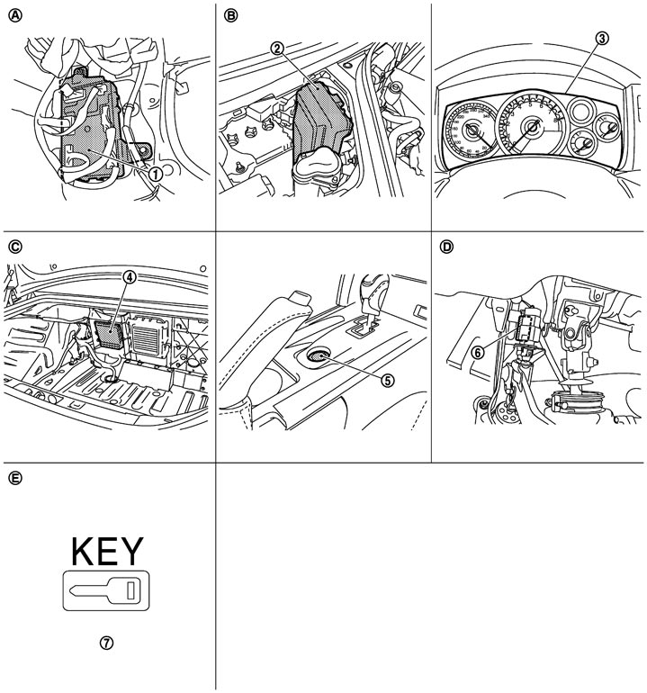
|
1. |
BCM M118, M119, M121, M122, M123 |
2. |
IPDM E/R E5, E6, F7 |
3. |
Combination meter M53 |
|
4. |
TCM B45 |
5. |
Push button ignition switch M131 |
6. |
Stop lamp switch E110 |
|
7. |
Combination meter (Key warning lamp) M53 |
|
|
|
|
|
A. |
Behind the instrument lower panel (RH) |
B. |
Engine room dash panel (RH) |
C. |
View with trunk front finisher removed |
|
D. |
View with instrument lower panel (driver) removed |
E. |
Located on the conbination meter |
|
|
Component Description
|
Component |
Reference |
|
IPDM E/R |
System Diagram
|
|
Ignition relay (built into IPDM E/R) |
Description
|
|
Ignition relay (inserted into fuse block) |
Description
|
|
Accessory relay |
Description
|
|
Blower relay |
Description
|
|
Stop lamp switch |
Description
|
|
TCM |
Description
|
|
Push-button ignition switch |
Description
|