TCM
TRANSMISSION: GR6Z30A
- Reference Value
- Wiring Diagram - TRANSMISSION CONTROL SYSTEM -
- Fail Safe
- DTC Inspection Priority Chart
- DTC Index
Reference Value
 VALUES ON THE DIAGNOSIS TOOL
- In CONSULT-III, the electrical shift timing, which is the operation timing of each solenoid, is displayed. Therefore, if there is an obvious difference between the shift timing estimated from a shift shock (or engine speed variations) and that shown on the CONSULT-III, the mechanical parts (including the hydraulic circuit) excluding the solenoids and sensors may be malfunctioning. In this case, check the mechanical parts following the appropriate diagnosis procedure.
- Shift point (gear position) displayed on CONSULT-III slightly differs from shift pattern described in Service Manual. This is due to the following reasons.
- Actual shift pattern may vary slightly within specified tolerances.
- While the shift pattern described in Service Manual indicates start of each shift, CONSULT-III shows gear position at the end of shift.
- CONSULT-III display of each solenoid (ON–OFF) changes at the start of shifting. Display of gear position changes at the end of shifting that is calculated by the control unit.
■ CAUTION ■
Each measurement must be performed at the transmission oil temperature of 50°C (122°F) or more.
|
Item name |
Condition |
Value / Status (Approx.) |
| SLEEVE B1 POSI 1 | Shift lever: P, N position | −1.7 – 1.7 mm (−0.067 – 0.067 in) |
| Shift lever: R position | −9.2 –−1.3 mm (−0.36 – 0.051 in) | |
| Running with 1st gear | 1.3 – 9.0 mm (0.051 – 0.354 in) | |
| Running with 2nd gear, 3rd gear, 4th gear, 5th gear, 6th gear (Other than M range, R mode) | −1.7 – 1.7 mm (−0.067 – 0.067 in) | |
| SLEEVE B1 POSI 2 | Shift lever: P, N position | −1.7 – 1.7 mm (−0.067 – 0.067 in) |
| Shift lever: R position | −9.2 –−1.3 mm (−0.36 – 0.051 in) | |
| Running with 1st gear | 1.3 – 9.0 mm (0.051 – 0.354 in) | |
| Running with 2nd gear, 3rd gear, 4th gear, 5th gear, 6th gear (Other than M range, R mode) | −1.7 – 1.7 mm (−0.067 – 0.067 in) | |
| SLEEVE A2 POSI | Shift lever: P, R, N position | −1.7 – 1.7 mm (−0.067 – 0.067 in) |
| Running with 1st gear, 2nd gear | 9.0 – 1.3 mm (0.354 – 0.051 in) | |
| Running with 3rd gear, 4th gear (Other than M range, R mode) | −9.2 –−1.3 mm (−0.36 –−0.051 in) | |
| Running with 5th gear, 6th gear (Other than M range, R mode) | −1.7 – 1.7 mm (−0.067 – 0.067 in) | |
| SLEEVE B2 POSI | Shift lever: P, R, or N position | 1.9 –−1.9 mm (0.075 –−0.075 in) |
| Running with 1st gear | 1.9 –−1.9 mm (0.075 –−0.075 in) | |
| Running with 2nd gear, 3rd gear (Other than M range, R mode) | 1.3 – 9.0 mm (0.051 – 0.354 in) | |
| Running with 4th gear, 5th gear, 6th gear (Other than M range, R mode) | −1.3 –−9.4 mm (−0.051 –−0.37 in) | |
| SLEEVE A1 POSI | Shift lever: P, R, or N position | −1.6 – 1.7 mm (−0.063 – 0.067 in) |
| Running with 1st gear, 2nd gear, 3rd gear, 4th gear | −1.6 – 1.7 mm (−0.063 – 0.067 in) | |
| Running with 5th gear, 6th gear (Other than M range, R mode) | 1.3 – 9.0 mm (0.051 – 0.354 in) | |
| ABS OPERATION SIG | ABS activated | On |
| Other than the above | Off | |
| ACCEL POSI SEN 1 | Closed throttle to wide-open throttle | 0.0/8 – 8.0/8 |
| MON SHIFT SOL 1 | Shift lever: P, R, N position | Off |
| When 2nd gear is released by selecting the shift lever from the A position to the N position (Release 2nd gear after selecting the shift lever from the A position to the N position). | On | |
Upshift
| ||
Downshift
| ||
| COMM SHIFT S/V 1 | Shift lever: P, R, N position | Off |
| When 2nd gear is released by selecting the shift lever from the A position to the N position (Release 2nd gear after selecting the shift lever from the A position to the N position). | On | |
Upshift
| ||
Downshift
| ||
| MON SHIFT SOL 2 | Shift lever: P, R, N position | Off |
| When 2nd gear is engaged by selecting the shift lever from the N position to the A position (Engage 2nd gear after selecting the shift lever from N position to A position). | On | |
Upshift
| ||
Downshift
| ||
| COMM SHIFT S/V 2 | Shift lever: P, R, N position | Off |
| When 2nd gear is engaged by selecting the shift lever from the N position to the A position (Engage 2nd gear after selecting the shift lever from N position to A position). | On | |
Upshift
| ||
Downshift
| ||
| MON SHIFT SOL 3 | Shift lever: P, N position | Off |
| On | |
Upshift
| ||
Downshift
| ||
| COMM SHIFT S/V 3 | Shift lever: P, N position | Off |
| On | |
Upshift
| ||
Downshift
| ||
| MON SHIFT SOL 4 | Shift lever: P, N position | Off |
| On | |
Upshift
| ||
Downshift
| ||
| COMM SHIFT S/V 4 | Shift lever: P, N position | Off |
| On | |
Upshift
| ||
Downshift
| ||
| FLUID TEMP | Ignition switch ON (5 seconds or more after turning the ignition switch ON) | The transmission oil temperature in the oil pan is displayed. |
| FLUID TEMP SEN | Transmission fluid temperature: 20°C (68°F) | 1,793 – 1,867 mV |
| Transmission fluid temperature: 50°C (122°F) | 1,096 – 1,150 mV | |
| Transmission fluid temperature: 80°C (176°F) | 573 – 617 mV | |
| COMM AXIS A S/V | Shift lever: P, N position (5 seconds or more after the engine is started with the shift lever in the P position and the message “T/M SYSTEM CHECK IN PROCESS” is not displayed on the information display) | 0.52 – 0.67 A |
| COMM AXIS B S/V | Shift lever: P, N position (5 seconds or more after the engine is started with the shift lever in the P position and the message “T/M SYSTEM CHECK IN PROCESS” is not displayed on the information display) | 0.52 – 0.67 A |
| STOP LAMP SW | Brake pedal depressed | On |
| Other than the above | Off | |
| CLUTCH A PRESS | Shift lever: P, N position (5 seconds or more after the engine is started with the shift lever in the P position and the message “T/M SYSTEM CHECK IN PROCESS” is not displayed on the information display) | 0.00 MPa |
| Running with reverse gear, 1st gear, 3rd gear, 5th gear | ||
| CLUTCH A SPEED |
| It is almost the same engine speed as the value indicated on the tachometer. |
| COM CLUTCH A S/V | Shift lever: P, N position (5 seconds or more after the engine is started with the shift lever in the P position and the message “T/M SYSTEM CHECK IN PROCESS” is not displayed on the information display) | 0.00 A |
| Running with reverse gear, 1st gear, 3rd gear, 5th gear | ||
| CLUTCH A TEMP | Ignition switch ON | The estimate temperature of clutch A is displayed. |
| CLUTCH B PRESS | Shift lever: P, N position (5 seconds or more after the engine is started with the shift lever in the P position and the message “T/M SYSTEM CHECK IN PROCESS” is not displayed on the information display) | 0.00 MPa |
| Running with 2nd gear, 4th gear, 6th gear | ||
| CLUTCH B SPEED |
| It is almost the same engine speed as the value indicated on the tachometer. |
| COM CLUTCH B S/V | Shift lever: P, N position (5 seconds or more after the engine is started with the shift lever in the P position and the message “T/M SYSTEM CHECK IN PROCESS” is not displayed on the information display) | 0.00 A |
| Running with 2nd gear, 4th gear, 6th gear | ||
| CLUTCH B TEMP | Ignition switch ON | The estimate temperature of clutch B is displayed. |
| GR POSITION | Shift lever: P, N position | N/P |
| Shift lever: R position | R | |
| While driving | 1, 2, 3, 4, 5, 6 | |
| ENGINE SPEED | Run the engine and compare the value indicated on CONSULT-III with the value indicated on the tachometer. | It is almost the same engine speed as the value indicated on the tachometer. |
| GR POSI INDICATION | Shift lever: P, N position | N/P |
| While driving | 1, 2, 3, 4, 5, 6 | |
| IGN SW | Ignition switch ON | On |
| Ignition switch OFF | Off | |
| LINE PRESSURE |
| 0.7 – 1.15 MPa |
| 0.85 – 1.15 MPa | |
| COM LINE PRES S/V |
| 0.61 – 0.83 A |
| 0.61 – 0.78 A | |
| COMM LUBE S/V |
| 1.20 A |
| When driving with the throttle opening 2.0/8 | 0 A | |
| AM RANGE CHG SW 1 | The shift lever is pressed to the M position side | Off |
| Other than the above | On | |
| AM RANGE CHG SW 2 | The shift lever is pressed to the M position side | On |
| Other than the above | Off | |
| MODE | Select the A range | A/N |
| SNOW of set-up switch (transmission) is selected at the A range. (SNOW lamp ON) | A/S | |
| R of set-up switch (transmission) is selected at the A range (R lamp ON) | A/R | |
| Select the M range | M/N | |
| R of set-up switch (transmission) is selected at the M range. (R lamp ON) | M/R | |
| COM R MODE LAMP | R of set-up switch (transmission) is selected (R lamp ON) | On |
| Other than the above | Off | |
| COM S MODE LMP | SNOW of set-up switch (transmission) is selected (SNOW lamp ON) | On |
| Other than the above | Off | |
| COM NEUTRAL SIG | Shift lever: P, N position | On |
| Other than the above | Off | |
| OUTPUT SHAFT SPD | While driving | It is almost the same speed as the value of the clutch A speed or clutch B speed divided by the gear ratio of the driving gear. |
| PARK POSITION SW | Shift lever: P position | On |
| Other than the above | Off | |
| RANGE | Shift lever: P position | P |
| Shift lever: R position | R | |
| Shift lever: N position | N | |
| Shift lever: A position | A | |
| Shift lever: M position | M | |
| COM BACK LMP RLY | Shift lever: R position | On |
| Other than the above | Off | |
| MON BACK LMP RLY | Shift lever: R position | On |
| Other than the above | Off | |
| MON SEQ S/V | Shift lever: P, R, N position | Off |
Upshift
| On | |
Downshift
| ||
| COMM SEQ S/V | Shift lever: P, R, N position | Off |
Upshift
| On | |
Downshift
| ||
| R MODE SW | With the knob of the set-up switch (transmission) pressed to the R side | On |
| Other than the above | Off | |
| SNOW MODE SW | With the knob of the set-up switch (transmission) pressed to the SNOW side | On |
| Other than the above | Off | |
| TR SENSOR No.0 | Shift lever: P position | On |
| Other than the above | Off | |
| TR SENSOR No.1 | Shift lever: R position | On |
| Other than the above | Off | |
| TR SENSOR No.2 | Shift lever: R, N position | On |
| Other than the above | Off | |
| TR SENSOR No.3 | Shift lever: N position | On |
| Other than the above | Off | |
| TR SENSOR No.4 | Shift lever; N, A, M position | On |
| Other than the above | Off | |
| TR SENSOR No.5 | Shift lever: A, M position | On |
| Other than the above | Off | |
| VEHICLE SPEED | Turn the drive wheel and compare the value indicated on CONSULT-III with the value indicated on the speedometer. | It is almost the same speed as the value indicated on the speedometer. |
| COM STARTER RLY | Shift lever: P, N position | On |
| Other than the above | Off | |
| MON STARTER RLY | Shift lever: P, N position | On |
| Other than the above | Off | |
| PADDLE SFT (DOWN) | The paddle shifter (shift-down switch) continues being pulled forward | On |
| Other than the above | Off | |
| PADDLE SFT (UP) | The paddle shifter (shift-up switch) continues being pulled forward | On |
| Other than the above | Off | |
| ACCEL POSI SEN 2 | Closed throttle to wide-open throttle | 0.0/8 – 8.0/8 |
| BATTERY VOLTAGE | Ignition switch ON (engine stopped) | Battery voltage (11 – 14 V) |
| VDC OPERATION SIG | VDC activated | On |
| Other than the above | Off | |
| TCM RELAY | Ignition switch ON | On |
| SHIFT LOCK SOL | “T/M SYSTEM CHECK IN PROCESS” is displayed on the information display in the combination meter when the shift lever is in P position. | On |
| Shift lever in any position other than P | Off |
TERMINAL LAYOUT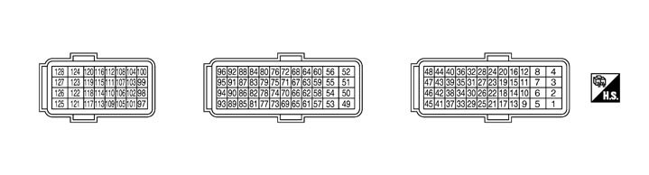 PHYSICAL VALUES
NOTE:
- TCM is installed to the back of the rear seatback. Remove the trim of the trunk room to check the input/output signal. Refer to Exploded View.
- Disconnect the TCM harness connector. Push the protrusion for fixing and fully open the lever (A) as shown in the figure when disconnecting the harness connector.
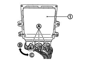
1 : TCM Direction B : Disconnect Direction C : Connect - The values in the table are the reference value measured between each terminal and ground.
|
Terminal No. (Wire color) |
Description |
Condition |
Value (Approx.) |
|||
|
+ |
− |
Signal name |
Input/Output |
|||
|
1 (W) |
4 |
BATT-2 |
Input |
Ignition switch ON |
Battery voltage (11 – 14 V) |
|
|
Ignition switch OFF |
0 V |
|||||
|
3 (B) |
Ground |
GND |
Output |
Always |
0 V |
|
|
4 (B) |
Ground |
GND |
Output |
Always |
0 V |
|
|
5 (W) |
4 |
BATT-3 |
Input |
Ignition switch ON |
Battery voltage (11 – 14 V) |
|
|
Ignition switch OFF |
0 V |
|||||
|
7 (B) |
Ground |
GND |
Output |
Always |
0 V |
|
|
8 (B) |
Ground |
GND |
Output |
Always |
0 V |
|
|
9 (P) |
4 |
BATT-1 |
Input |
Always |
Battery voltage (11 – 14 V) |
|
|
10 (LG) |
4 |
Back-up lamp signal |
Output |
Ignition switch ON |
Shift lever: R position |
0 V |
|
Other than the above |
Battery voltage (11 – 14 V) |
|||||
|
11 (L) |
— |
CAN-H |
Input/Output |
— |
— |
|
|
14 (V) |
4 |
Power OFF |
Output |
Ignition switch ON |
0 V |
|
|
Ignition switch OFF |
Battery voltage (11 – 14 V) |
|||||
|
15 (P) |
— |
CAN-L |
Input/Output |
— |
— |
|
|
16 (W) |
4 |
Stop lamp switch signal |
Input |
Ignition switch ON |
Brake pedal depressed |
Battery voltage (11 – 14 V) |
|
Other than the above |
0 V |
|||||
|
17 (Y) |
4 |
Ignition switch signal |
Input |
Ignition switch ON |
Battery voltage (11 – 14 V) |
|
|
Ignition switch OFF |
0 V |
|||||
|
19 (GR) |
4 |
Starter relay signal |
Output |
Ignition switch ON |
Shift lever: P, N position |
Battery voltage (11 – 14 V) |
|
Other than the above |
0 V |
|||||
|
23 (BR) |
4 |
Auto/manual range change switch 1 signal |
Input |
Ignition switch ON |
The shift lever is pressed to the M position side |
0 V |
|
Other than the above |
5 V |
|||||
|
25 (L) |
4 |
Range sensor power source 1 |
Output |
Ignition switch ON |
5 V |
|
|
Ignition switch OFF |
0 V |
|||||
|
26 (LG) |
4 |
Range sensor power source 2 |
Output |
Ignition switch ON |
5 V |
|
|
Ignition switch OFF |
0 V |
|||||
|
27 (G) |
4 |
Range sensor No.0 signal |
Input |
Ignition switch ON |
Shift lever: P position |
0 V |
|
Other than the above |
5 V |
|||||
|
28 (V) |
4 |
Auto/manual range change switch 2 signal |
Input |
Ignition switch ON |
The shift lever is pressed to the M position side |
5 V |
|
Other than the above |
0 V |
|||||
|
31 (SB) |
4 |
Engine speed signal |
Input |
After engine warming up |
At idle NOTE: The pulse period changes depending on the idle speed |
1 V*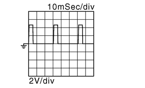 |
|
Engine speed: 2000 rpm |
1 V*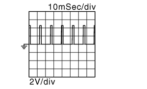 |
|||||
|
33 (V) |
4 |
Range sensor No.1 signal |
Input |
Ignition switch ON |
Shift lever: R position |
0 V |
|
Other than the above |
5 V |
|||||
|
34 (O) |
4 |
SNOW mode switch signal |
Input |
Ignition switch ON |
With the knob of the set-up switch (transmission) pressed to the SNOW side |
0 V |
|
Other than the above |
5 V |
|||||
|
35 (G) |
4 |
Range sensor No.3 signal |
Input |
Ignition switch ON |
Shift lever: N position |
0 V |
|
Other than the above |
5 V |
|||||
|
37 (GR) |
4 |
R mode switch signal |
Input |
Ignition switch ON |
With the knob of the set-up switch (transmission) pressed onto the R side |
0 V |
|
Other than the above |
5 V |
|||||
|
38 (R) |
4 |
Range sensor No.2 signal |
Input |
Ignition switch ON |
Shift lever: R, N position |
0 V |
|
Other than the above |
5 V |
|||||
|
39 (W) |
4 |
Paddle shifter (shift-up switch) signal |
Input |
Ignition switch ON |
The paddle shifter (shift-up switch) continues being pulled forward |
0 V |
|
Other than the above |
Battery voltage (11 – 14 V) |
|||||
|
42 (L) |
4 |
Paddle shifter (shift-down switch) signal |
Input |
Ignition switch ON |
The paddle shifter (shift-down switch) continues being pulled forward |
0 V |
|
Other than the above |
Battery voltage (11 – 14 V) |
|||||
|
43 (P) |
4 |
Range sensor No.4 signal |
Input |
Ignition switch ON |
Shift lever; N, A, M position |
0 V |
|
Other than the above |
5 V |
|||||
|
44 (GR) |
4 |
Range sensor No.5 signal |
Input |
Ignition switch ON |
Shift lever: A, M position |
0 V |
|
Other than the above |
5 V |
|||||
|
45 (O) |
4 |
R mode lamp signal |
Input |
Ignition switch ON |
R of set-up switch (transmission) is selected (R lamp ON) |
0 V |
|
Other than the above |
Battery voltage (11 – 14 V) |
|||||
|
46 (W) |
4 |
Shift lock solenoid control signal |
Output |
Ignition switch ON |
|
Battery voltage (11 – 14 V) |
|
Other than the above |
0 V |
|||||
|
47 (G) |
4 |
SNOW mode lamp signal |
Input |
Ignition switch ON |
SNOW of set-up switch (transmission) is selected (SNOW lamp ON) |
0 V |
|
Other than the above |
Battery voltage (11 – 14 V) |
|||||
|
49 (L) |
4 |
Shift solenoid valve 1 (+) |
Output |
Engine running |
Shift lever: P, R, or N position |
0 V |
|
While driving (Other than M range, R mode) |
When 2nd gear is released by selecting the shift lever from the A position to the N position (Release 2nd gear after selecting the shift lever from the A position to the N position). |
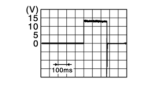
|
||||
|
Upshift
|
||||||
|
Downshift
|
||||||
|
51 (P) |
4 |
Shift solenoid valve 3 (+) |
Output |
Engine running |
Shift lever: P, N position |
0 V |
|
While driving (Other than M range, R mode) |
|
|
||||
|
Upshift
|
||||||
|
Downshift
|
||||||
|
53 (GR) |
4 |
Sequence solenoid valve (+) |
Output |
Engine running |
Shift lever: P, R, N position |
0 V |
|
While driving (Other than the M range, R mode) |
Upshift
|
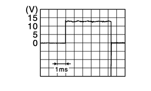
|
||||
|
Downshift
|
||||||
|
54 (W) |
4 |
Shift solenoid valve 2 (+) |
Output |
Engine running |
Shift lever: P, R, N position |
0 V |
|
While driving (Other than the M range, R mode) |
When 2nd gear is engaged by selecting the selector gear from the N position to the A position (Engage 2nd gear after selecting the shift lever from the N position to the A position). |
|
||||
|
Upshift
|
||||||
|
Downshift
|
||||||
|
56 (LG) |
4 |
Shift solenoid valve 4 (+) |
Output |
Engine running |
Shift lever: P, N position |
0 V |
|
While driving (Other than M range, R mode) |
|
|
||||
|
Upshift
|
||||||
|
Downshift
|
||||||
|
57 (BR) |
4 |
Axis A feed pressure solenoid valve (+) |
Output |
Engine running |
5 seconds or more after the engine is started with the shift lever in the P position and the message “T/M SYSTEM CHECK IN PROCESS” is not displayed on the information display |
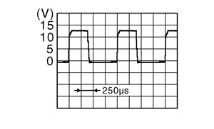
|
|
59 (G) |
4 |
Axis B feed pressure solenoid valve (+) |
Output |
Engine running |
5 seconds or more after the engine is started with the shift lever in P position and the message “T/M SYSTEM CHECK IN PROCESS” is not displayed on the information display |
|
|
62 (R) |
4 |
Axis A feed pressure solenoid valve (−) |
Input |
Always |
0 V |
|
|
64 (O) |
4 |
Axis B feed pressure solenoid valve (−) |
Input |
Always |
0 V |
|
|
66 (R) |
4 |
6th-Neutral position sensor (−) |
Input |
Always |
0 V |
|
|
67 (L) |
4 |
1st-Reverse position sensor 1 signal |
Input |
Engine running |
Shift lever: P, N position |
2.19 – 2.88 V |
|
Shift lever: R position |
0.68 – 1.76 V |
|||||
|
While driving |
1st gear |
3.34 – 4.41 V |
||||
|
2nd gear, 3rd gear, 4th gear, 5th gear, 6th gear (Other than M range, R mode) |
2.19 – 2.88 V |
|||||
|
68 (BR) |
4 |
Clutch A speed sensor (−) |
Input |
Always |
0 V |
|
|
69 (Y) |
4 |
1st-Reverse position sensor 2 (−) |
Input |
Always |
0 V |
|
|
70 (W) |
4 |
6th-Neutral position sensor signal |
Input |
Engine running |
Shift lever: P, R, N position |
2.19 – 2.88 V |
|
While driving |
1st gear, 2nd gear, 3rd gear, 4th gear |
|||||
|
5th gear, 6th gear (Other than M range, R mode) |
0.68 – 1.76 V |
|||||
|
71 (Y) |
4 |
1st-Reverse position sensor 1 (+) |
Output |
Ignition switch ON |
5 V |
|
|
Ignition switch OFF |
0 V |
|||||
|
72 (G) |
4 |
Clutch A speed sensor signal |
Input |
|
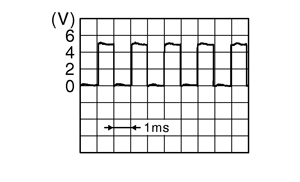
|
|
|
73 (Y) |
4 |
Line pressure sensor (+) |
Output |
Ignition switch ON |
5 V |
|
|
Ignition switch OFF |
0 V |
|||||
|
74 (BR) |
4 |
6th-Neutral position sensor (+) |
Output |
Ignition switch ON |
5 V |
|
|
Ignition switch OFF |
0 V |
|||||
|
75 (L) |
4 |
1st-Reverse position sensor 2 (+) |
Output |
Ignition switch ON |
5 V |
|
|
Ignition switch OFF |
0 V |
|||||
|
76 (Y) |
4 |
Clutch A speed sensor (+) |
Output |
Ignition switch ON |
5 V |
|
|
Ignition switch OFF |
0 V |
|||||
|
77 (GR) |
4 |
Line pressure sensor signal |
Input |
Engine running |
|
0.84 – 1.97 V |
|
78 (R) |
4 |
Clutch B speed sensor (+) |
Output |
Ignition switch ON |
5 V |
|
|
Ignition switch OFF |
0 V |
|||||
|
79 (G) |
4 |
1st-Reverse position sensor 2 signal |
Input |
Engine running |
Shift lever: P, N position |
2.19 – 2.88 V |
|
Shift lever: R position |
3.34 – 4.41 V |
|||||
|
While driving |
1st gear |
0.68 – 1.76 V |
||||
|
2nd gear, 3rd gear, 4th gear, 5th gear, 6th gear (Other than M range, R mode) |
2.19 – 2.88 V |
|||||
|
80 (BR) |
4 |
Line pressure sensor (−) |
Input |
Always |
2.19 – 2.88 V |
|
|
81 (G) |
4 |
2nd-4th position sensor (+) |
Output |
Ignition switch ON |
5 V |
|
|
Ignition switch OFF |
0 V |
|||||
|
82 (W) |
4 |
Clutch B speed sensor signal |
Input |
|
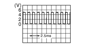
|
|
|
83 (L) |
4 |
2nd-4th position sensor (−) |
Input |
Always |
0 V |
|
|
84 (BR) |
4 |
3rd-5th position sensor (−) |
Input |
Always |
0 V |
|
|
85 (Y) |
4 |
2nd-4th position sensor signal |
Input |
Engine running |
Shift lever: P, R, N position |
2.19 – 2.88 V |
|
While driving |
1st gear, 2nd gear |
0.68 – 1.76 V |
||||
|
3rd gear, 4th gear (Other than M range, R mode) |
3.34 – 4.41 V |
|||||
|
5th gear, 6th gear (Other than M range, R mode) |
2.19 – 2.88 V |
|||||
|
86 (L) |
4 |
Clutch B speed sensor (−) |
Input |
Always |
0 V |
|
|
87 (L) |
4 |
Fluid temperature sensor (+) |
Output |
Ignition switch ON |
Transmission fluid temperature: 20°C (68°F) |
1.80 – 1.86 V |
|
Transmission fluid temperature: 50°C (122°F) |
1.10 – 1.15 V |
|||||
|
Transmission fluid temperature: 80°C (176°F) |
0.58 – 0.61 V |
|||||
|
88 (W) |
4 |
3rd-5th position sensor (+) |
Output |
Ignition switch ON |
5 V |
|
|
Ignition switch OFF |
0 V |
|||||
|
89 (O) |
4 |
Park position switch signal |
Input |
Ignition switch ON |
Shift lever: P position |
0 V |
|
Other than the above |
5 V |
|||||
|
91 (SB) |
4 |
Fluid temperature sensor (−) |
Input |
Always |
0 V |
|
|
92 (R) |
4 |
3rd-5th position sensor signal |
Input |
Engine running |
Shift lever: P, R, N position |
2.19 – 2.88 V |
|
While driving |
1st gear |
|||||
|
2nd gear, 3rd gear (Other than M range, R mode) |
0.68 – 1.76 V |
|||||
|
4th gear, 5th gear, 6th gear (Other than M range, R mode) |
3.34 – 4.41 V |
|||||
|
94 (G) |
4 |
1st-Reverse position sensor 1 (−) |
Input |
Always |
0 V |
|
|
97 (BR) |
4 |
Clutch A pressure sensor (+) |
Output |
Ignition switch ON |
5 V |
|
|
Ignition switch OFF |
0 V |
|||||
|
98 (R) |
4 |
Clutch A pressure sensor signal |
Input |
Engine running |
Shift lever: P, R, N position |
0.38 – 0.64 V |
|
While driving |
1st gear, 3rd gear, 5th gear |
|||||
|
99 (W) |
4 |
Clutch A pressure sensor (−) |
Input |
Always |
0 V |
|
|
102 (Y) |
4 |
Clutch B pressure sensor (+) |
Output |
Ignition switch ON |
5 V |
|
|
Ignition switch OFF |
0 V |
|||||
|
103 (L) |
4 |
Clutch B pressure sensor signal |
Input |
Engine running |
Shift lever: P, R, N position |
0.38 – 0.64 V |
|
While driving |
2nd gear, 4th gear, 6th gear |
|||||
|
104 (G) |
4 |
Clutch B pressure sensor (−) |
Input |
Always |
0 V |
|
|
105 (L) |
4 |
Output shaft speed sensor (+) |
Output |
Ignition switch ON |
5 V |
|
|
Ignition switch OFF |
0 V |
|||||
|
106 (G) |
4 |
Output shaft speed sensor signal |
Input |
|
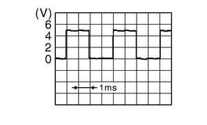
|
|
|
107 (Y) |
4 |
Output shaft speed sensor (−) |
Input |
Always |
0 V |
|
|
113 (O) |
4 |
Line pressure solenoid valve (−) |
Input |
Always |
0 V |
|
|
115 (W) |
4 |
Lubricating flow solenoid valve (−) |
Input |
Always |
0 V |
|
|
118 (V) |
4 |
Line pressure solenoid valve (+) |
Output |
Engine running |
|
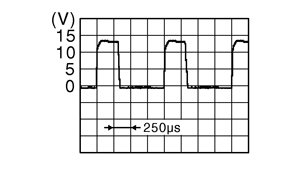
|
|
120 (BR) |
4 |
Lubricating flow solenoid valve (+) |
Output |
Engine running |
|
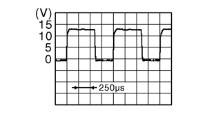
|
|
121 (R) |
4 |
Clutch A solenoid valve (+) |
Output |
Other than running with 2nd gear, 4th gear, 6th gear (Clutch A is not engaged) |
0 V |
|
|
123 (G) |
4 |
Clutch B solenoid valve (+) |
Output |
Other than running with reverse gear, 1st gear, 3rd gear, 5th gear (Clutch B is not engaged) |
0 V |
|
|
126 (LG) |
4 |
Clutch A solenoid valve (−) |
Input |
Always |
0 V |
|
|
128 (Y) |
4 |
Clutch B solenoid valve (−) |
Input |
Always |
0 V |
|
Wiring Diagram - TRANSMISSION CONTROL SYSTEM -
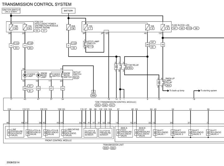
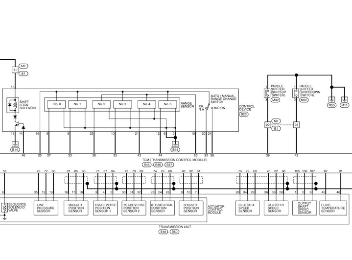
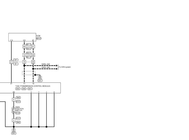
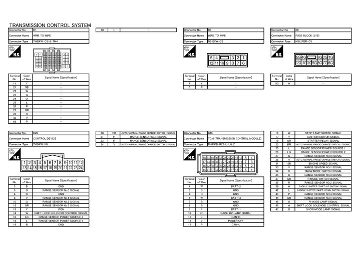
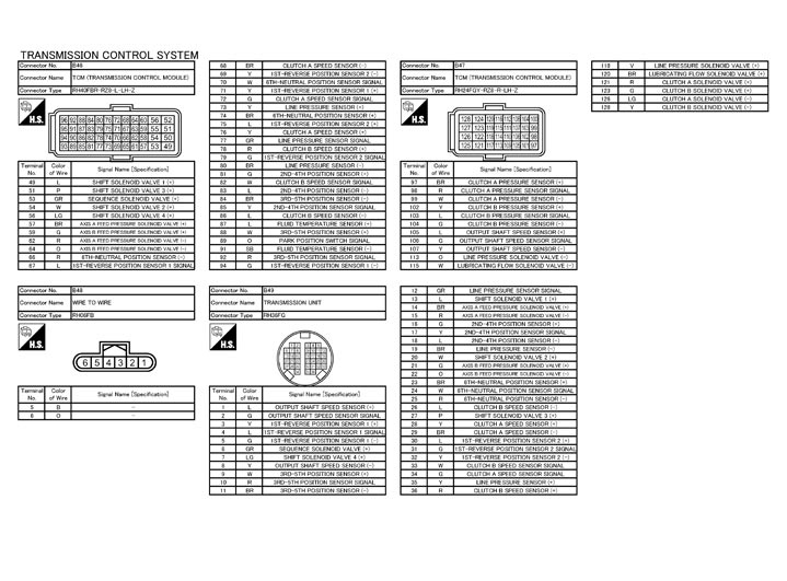
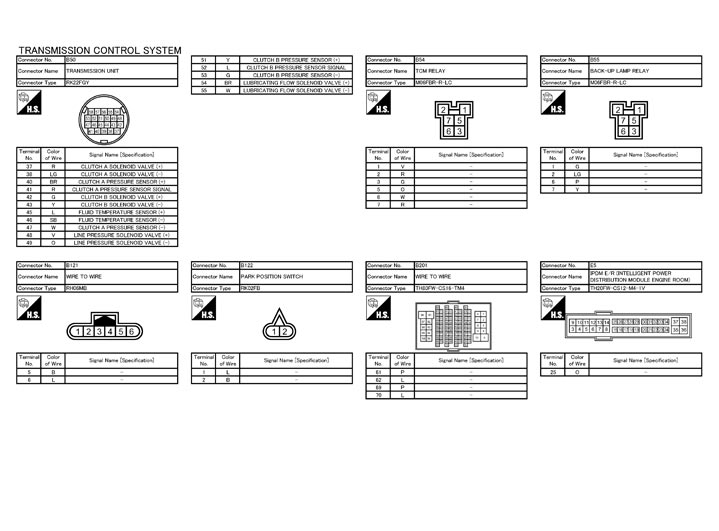
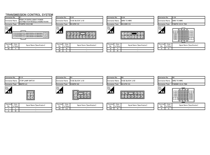
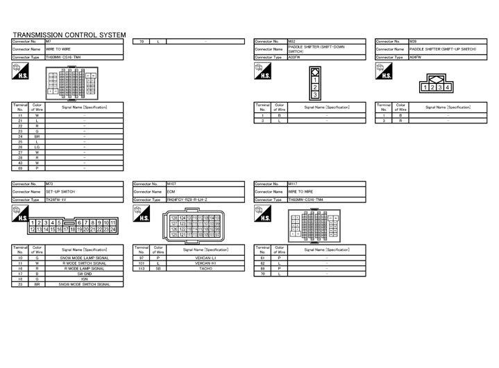
Fail Safe
PRECAUTION REGARDING FAIL SAFE FUNCTIONSTCM has the electrical fail safe mode. The mode functions so that the operation can be continued even if the signal circuit of the main electronically controlled input/output parts is damaged.
Even if the electronic circuit is normal, the fail safe mode may start under special conditions (such as when the brake pedal is depressed suddenly from a hard wheel spin status to stop rotation of wheels). In this case, turn the ignition switch OFF and back to ON after 5 seconds to resume the normal shift pattern.
Consequently, the customer's vehicle may already returns to normal condition. Refer to Work Flow (GT-R certified NISSAN dealer). Following are results of self-diagnosis.
FAIL SAFE FUNCTIONIf a malfunction occurs in either of the sensors or solenoids, this function controls the normal operation without downgrading the drivability.
| DTC No. | The transmission operates under the fail safe mode | ||||||
| P0700*1 P0705 | Release the clutches A and B if an error is detected. The driving force is not transmitted caused by this. The vehicle cannot be driven. | ||||||
| P0770 P0882 | Driving gear | Fixed into the driving gear to get the vehicle driven, if an error occurs.
| |||||
| Driving gear when the error occurs | Restart | ||||||
| 1st gear | Possible to drive forward only (fixed into 1st gear) | ||||||
| 2nd gear | Only moving forward is possible (fixed into 2nd gear) | ||||||
| 3rd gear, 4th gear, 5th gear, 6th gear, Neutral, Not identified | Impossible | ||||||
| Reverse | Only moving rearward is possible (fixed into Reverse gear) | ||||||
| Driving mode |
| ||||||
| Vehicle speed | The engine torque is restricted by the driving gear when the error occurs, and then the vehicle speed (maximum speed) is restricted. | ||||||
| Driving gear when the error occurs | Vehicle speed km/h (MPH) | ||||||
| 1st gear, 2nd gear | 46 (29) | ||||||
| 3rd gear, 4th gear | 85 (53) | ||||||
| 5th gear, 6th gear | 134 (84) | ||||||
| Reverse | 46 (29) | ||||||
| Neutral | 134 (84) | ||||||
| Not identified | 46 (46) | ||||||
| P0700*2 P0715 P0729 P0732 P0745 P0746 P0750 P0755 P0795 P0797 P0840 | Driving gear |
| |||||
| Driving mode |
| ||||||
| Vehicle speed | The engine torque is restricted by the driving gear when the error occurs, and then the vehicle speed (maximum speed) is restricted. | ||||||
| Driving gear when the error occurs | Vehicle speed km/h (MPH) | ||||||
| 2nd gear | 46 (29) | ||||||
| 4th gear | 85 (53) | ||||||
| 6th gear | 134 (84) | ||||||
| Neutral | 134 (84) | ||||||
| Not identified | 46 (29) | ||||||
| P0700*2 P0731 P0733 P0760 P0765 P0775 P0776 P0845 P2713 P2714 P2765 | Driving gear |
| |||||
| Driving mode |
| ||||||
| Vehicle speed | The engine torque is restricted by the driving gear when the error occurs, and then the vehicle speed (maximum speed) is restricted. | ||||||
| Driving gear when the error occurs | Vehicle speed km/h (MPH) | ||||||
| 1st gear | 46 (29) | ||||||
| 3rd gear | 85 (53) | ||||||
| 5th gear | 134 (84) | ||||||
| Reverse | 46 (29) | ||||||
| Neutral | 134 (84) | ||||||
| Unknown | 46 (29) | ||||||
| P0700*3, *4 P0705 P1705 | Driving gear | The use of all gears becomes possible. | |||||
| Driving mode |
| ||||||
| Vehicle speed | Restrict or fix the engine torque and fix the throttle position according to the detected DTC. | ||||||
| DTC | Engine torque | Throttle position | |||||
| P0700*3 | Fixed | Approximately 1/8 fixed | |||||
| P0700*4 | Restricted | As per usual | |||||
| P0705 | Restricted | As per usual | |||||
| P1705 | Fixed | Approximately 1/8 fixed | |||||
DTC Inspection Priority Chart
When multiple DTCs are detected simultaneously, check one by one as per the following priority list.
| Priority | Detected items (DTC) |
| 1 |
|
| 2 |
|
| 3 |
|
| 4 |
|