CONTROL DEVICE
TRANSMISSION: GR6Z30A
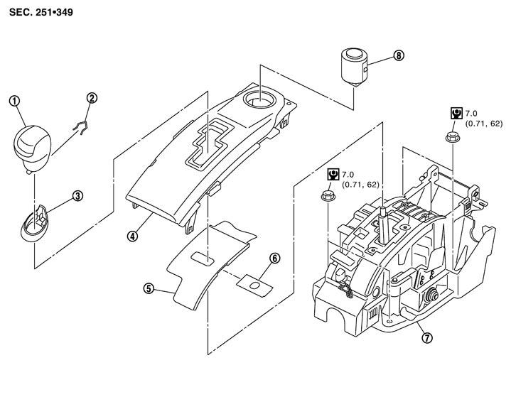
Exploded View
|
1. |
Shift lever knob |
2. |
Lock pin |
3. |
Knob cover |
|
4. |
Position indicator lamp |
5. |
Slide cover |
6. |
Slide plate |
|
7. |
Control device assembly |
8. |
Push-button ignition switch |
|
|
|
Refer to Components in GI section for the symbols shown in the figure. |
|||||
Removal and Installation
■ CAUTION ■
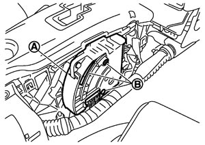
Be careful of the following items because the range sensor is an important device to detect the shift lever position.- Keep range sensor (A) away from magnetic cards and magnetic objects during work.
- For a person with an electro-medical apparatus, keep the range sensor away from the device.
- Keep foreign objects away from the opening (B) of range sensor during work.
- Never touch the range sensor and sensor mounting screw.
- Always shift the shift lever to the P position during work.
 REMOVAL
- 1.Shift the shift lever to the P position.
- 2.Lower the rear side of the knob cover (1) downward.
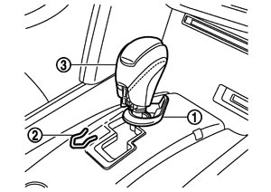
- 3.Pull out the lock pin (2) from the shift lever knob (3).
- 4.Remove the shift lever knob and the knob cover.
- 5.Remove the console finisher assembly, instrument side panel LH/RH, and center console assembly. Refer to Exploded View.
- 6.Disconnect the control cable from the control device assembly. Refer to Exploded View (GT-R certified NISSAN dealer).
- 7.Disconnect the push-button ignition switch connector and the range sensor connector, and remove the harness clip.
- 8.Remove the control device assembly mounting bolt.
- 9.Remove the control device assembly from the vehicle.
■ CAUTION ■
Never place the control device assembly upside-down after removal. In addition, never place the range sensor side down. INSTALLATIONNote the following, and install in the reverse order of removal.
- Refer to “ADJUSTMENT” in Inspection and Adjustment when installing the control cable to the control device assembly.
- Note the following items when installing the shift lever knob.
- Install the lock pin (1) to the shift lever knob (2).
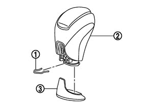
- Install the knob cover (3) to the shift lever knob.
- Insert the shift lever knob into the shift lever until it clicks.
Disassembly and Assembly
DISASSEMBLY■ CAUTION ■
Always shift the shift lever in the N position when performing disassembly and assembly of control device assembly.
- 1.Press the shift lock release button, and then shift the shift lever in the N position.
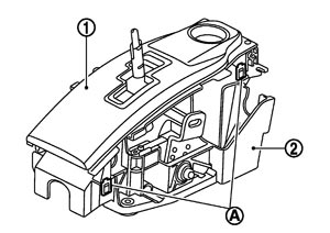
- 2.Insert a screwdriver into tabs (A: 4 locations), and remove the position indicator plate (1) from the control device assembly (2) while lifting it up.
■ CAUTION ■
The tabs crack easily. Be careful when removing.- 3.Remove the starter switch from the position indicator plate.
- 4.Remove the slide cover from the control device assembly.
AssemblyNote the following, and assemble in the reverse order of disassembly.
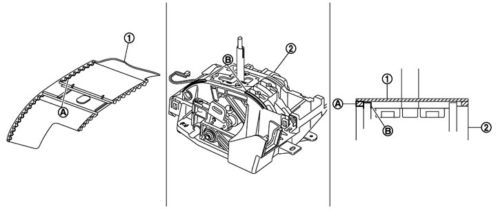
- Align the convex area (A) of slide cover (1) with the convex area (B) of control device assembly (2) as shown in the figure, and then install the position indicator plate. Check the shift lever movement after installation. Assemble again if any malfunctioning condition is detected.
Inspection
INSPECTION AFTER INSTALLATIONCheck the shift position after installation. Adjust the shift position if any malfunctioning condition is detected. Refer to Inspection and Adjustment.