PREPARATION
Special Service Tools
| Tool number (Kent-Moore No.) Tool name | Description | |
| KV10116200 (J26336-A) Valve spring compressor 1. KV10115900 (J26336-20) Attachment 2.KV10109220 ( — ) Adapter | 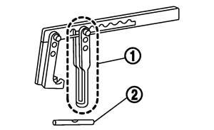 | Disassembling valve mechanism Part (1) is a component of KV10116200 (J26336-A), but Part (2) is not so. |
| KV10107902 (J38959) Valve oil seal puller | 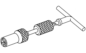 | Replacing valve oil seal |
| KV10115600 (J-38958) Valve oil seal drift | 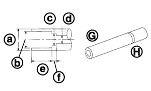 | Installing valve oil seal Use side A (G). a: 20 (0.79) dia. d: 8 (0.31) dia. b: 13 (0.51) dia. e: 10.7 (0.421) c: 10.3 (0.406) dia. f: 5 (0.20) H: side B Unit: mm (in) |
| EM03470000 (J8037) Piston ring compressor | 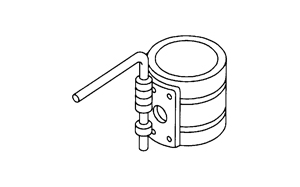 | Installing piston assembly into cylinder bore |
| KV10111100 (J37228) Seal cutter | 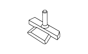 | Removing oil pan (lower), front and rear timing chain case, etc. |
| KV10112100 (BT8653-A) Angle wrench | 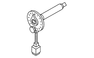 | Tightening bolts for connecting rod bearing cap, cylinder head, etc. in angle |
| KV10111710 (J3647-A) Heated oxygen sensor wrench | 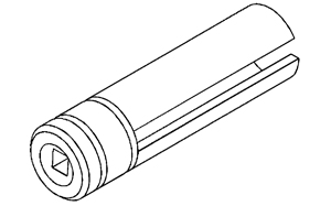 | Loosening or tightening air fuel ratio sensor 1 For 22 mm (0.87 in) width hexagon nut |
| KV10114400 (J-38365) Heated oxygen sensor wrench | 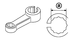 | Loosening or tightening heated oxygen senor 2 a: 22 mm (0.87 in) |
| KV101056S0 (J-49374) Ring gear stopper | 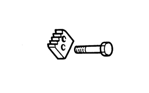 | Fixing flywheel |
| KV10119100 (J-49360) Resin gasket scraper | 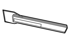 | Liquid gasket scraper for oil pan (upper) |
Commercial Service Tools
|
(Kent-Moore No.) Tool name |
|
Description |
|
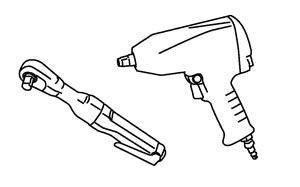
( — ) Power tool |
|
Loosening nuts and bolts |
|
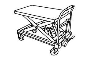
( — ) Manual lift table caddy |
|
Removing and installing engine |
|
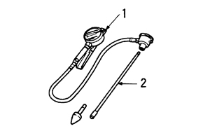
( — ) 1.Compression gauge 2.Adapter |
|
Checking compression pressure |
|
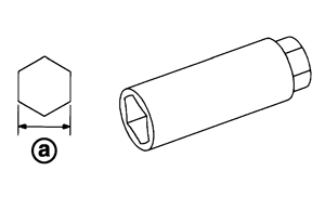
( — ) Spark plug wrench |
|
Removing and installing spark plug a: 14 mm (0.55 in) |
|
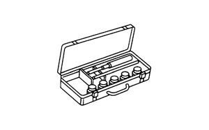
( — ) Valve seat cutter set |
|
Finishing valve seat dimensions |
|
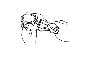
( — ) Piston ring expander |
|
Removing and installing piston ring |
|
( — ) Valve guide drift |
|
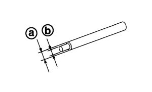
Removing and installing valve guide Intake and Exhaust: a: 9.5 mm (0.374 in) dia. b: 5.5 mm (0.217 in) dia. |
|
( — ) Valve guide reamer |
|
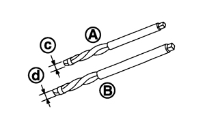
A: Reaming valve guide inner hole B: Reaming hole for oversize valve guide Intake and Exhaust: c: 6.0 mm (0.236 in) dia. d: 10.2 mm (0.402 in) dia. |
|
(J-43897-18) (J-43897-12) Oxygen sensor thread cleaner |
|
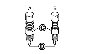
Reconditioning the exhaust system threads before installing a new air fuel ratio sensor and heated oxygen sensor (Use with anti-seize lubricant shown below.) A: J-43897-18 [18 mm (0.71 in) dia.] for zirconia heated oxygen sensor and air fuel ratio sensor B: J-43897-12 [12 mm (0.47 in) dia.] for titania heated oxygen sensor C: Mating surface shave cylinder D: Flutes |
|
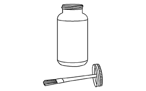
( — ) Anti-seize lubricant (Permatex 133AR or equivalent meeting MIL specification MIL-A-907) |
|
Lubricating oxygen sensor thread cleaning tool when reconditioning exhaust system threads |