CAMSHAFT VALVE CLEARANCE
 INSPECTION
Perform inspection as follows after removal, installation or replacement of camshaft or valve-related parts, or if there is unusual engine conditions regarding valve clearance.
In cases of removing/installing or replacing camshaft and valve-related parts, or of unusual engine conditions due to changes in valve clearance (found malfunctions during stating, idling or causing noise), perform inspection as follows:
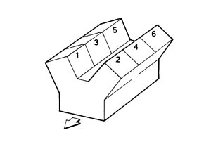
 | : Engine front |
- 1.Remove rocker covers (bank 1 and bank 2). Refer to Exploded View.
- 2.Measure the valve clearance as follows:
- Rotate crankshaft pulley clockwise to align timing mark (grooved line without color) with timing indicator (1).
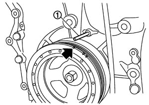

: Timing mark (grooved line without color) NOTE:Timing indicator is not included because it is not factory-supplied. - Check that intake and exhaust cam nose on No. 1 cylinder (engine front side of bank 1) are located as shown in the figure.
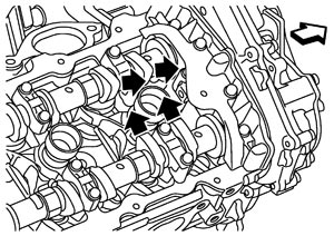
- If not, turn crankshaft one revolution (360 degrees) and align as shown in the figure.
: Engine front - By referring to the figure, measure the valve clearances at locations marked “×” as shown in the table below (locations indicated in the figure).
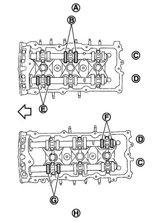
: Engine front - No. 1 cylinder at compression TDC
Measuring position [bank 1 (A)] No. 1 CYL. No. 3 CYL. No. 5 CYL. No. 1 cylinder at compression TDC EXH (C) × (B) INT (D) × (E) Measuring position [bank 2 (H)] No. 2 CYL. No. 4 CYL. No. 6 CYL. No. 1 cylinder at compression TDC INT (D) × (F) EXH (C) × (G) - By referring to the figure, measure the valve clearances at locations marked “×” as shown in the table below (locations indicated in the figure).
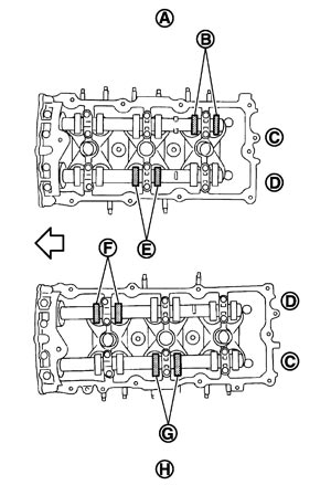
: Engine front - No. 3 cylinder at compression TDC
Measuring position [bank 1 (A)] No. 1 CYL. No. 3 CYL. No. 5 CYL. No. 3 cylinder at compression TDC EXH (C) × (B) INT (D) × (E) Measuring position [bank 2 (H)] No. 2 CYL. No. 4 CYL. No. 6 CYL. No. 3 cylinder at compression TDC INT (D) × (F) EXH (C) × (G) - By referring to the figure, measure the valve clearances at locations marked “×” as shown in the table below (locations indicated in the figure).
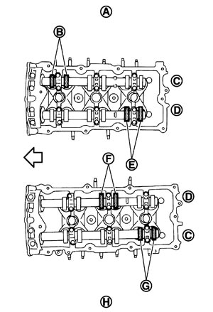
: Engine front - No. 5 cylinder at compression TDC
Measuring position [bank 1 (A)] No. 1 CYL. No. 3 CYL. No. 5 CYL. No. 5 cylinder at compression TDC EXH (C) × (B) INT (D) × (E) Measuring position [bank 2 (H)] No. 2 CYL. No. 4 CYL. No. 6 CYL. No. 5 cylinder at compression TDC INT (D) × (F) EXH (C) × (G)
-
(1)Set No. 1 cylinder at TDC of its compression stroke.
-
(2)Use a feeler gauge, measure the clearance between valve lifter and camshaft.
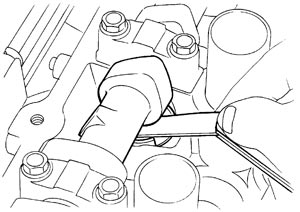
| Valve clearance | : Refer to Camshaft (GT-R certified NISSAN dealer). |
-
(3)Rotate crankshaft by 240 degrees clockwise (when viewed from engine front) to align No. 3 cylinder at TDC its compression stroke.
NOTE:
Mark a position 240 degrees (b) from a corner of the hexagonal part of crankshaft pulley mounting bolt as shown in the figure. Use the hexagonal part as a guide.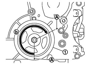
| 1 | : Crankshaft pulley |
| A | : Paint mark |
-
(4)Rotate crankshaft by 240 degrees clockwise (when viewed from engine front) to align No. 5 cylinder at TDC of compression stroke.
NOTE:
Mark a position 240 degrees (b) from a corner of the hexagonal part of crankshaft pulley mounting bolt as shown in the figure. Use the hexagonal part as a guide.| 1 | : Crankshaft pulley |
| A | : Paint mark |
- 3.Perform adjustment if the measured value is out of the standard. Refer to Inspection (GT-R certified NISSAN dealer).