INTAKE MANIFOLD COLLECTOR
Exploded View
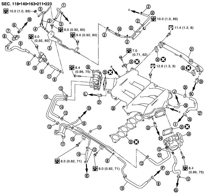
|
1. |
EVAP hose |
2. |
Clamp |
3. |
EVAP tube (bank 1) |
|
4. |
EVAP connector hose |
5. |
EVAP tube (front) |
6. |
EVAP hose |
|
7. |
Vacuum tank (service port) |
8. |
Clamp |
9. |
EVAP hose |
|
10. |
EVAP canister purge control solenoid valve |
11. |
EVAP hose |
12. |
Clamp |
|
13. |
Water hose |
14. |
Water hose |
15. |
Spacer |
|
16. |
Water tube and vacuum tube assembly |
17. |
Vacuum hose |
18. |
Water hose |
|
19. |
Vacuum hose |
20. |
Water hose |
21. |
Water hose |
|
22. |
Gasket |
23. |
Vacuum hose |
24. |
Electric throttle control actuator (bank 2) |
|
25. |
Gasket |
26. |
Clamp |
27. |
PCV hose |
|
28. |
Vacuum hose |
29. |
Vacuum hose |
30. |
Gasket |
|
31. |
Balance tube |
32. |
EVAP hose |
33. |
EVAP tube (bank 2) |
|
34. |
EVAP connector hose |
35. |
Manifold absolute Pressure (MAP) sensor |
36. |
Electric throttle control actuator (bank 1) |
|
37. |
Vacuum hose |
38. |
Intake manifold collector |
|
|
|
B. |
To centralized under-floor piping |
D. |
To exhaust manifold and turbocharger (bank 1) |
E. |
To water outlet (front) |
|
F. |
To turbocharger boost control solenoid valve |
G. |
To heater pipe |
H. |
To recirculation valve (bank 2) |
|
I. |
To breather separator assembly |
J. |
To pressure regulator and fuel hose assembly |
K. |
To brake booster |
|
L. |
To recirculation valve (bank 1) |
|
|
|
|
|
Refer to Components for symbols in the figure. |
|||||
Removal and Installation
 REMOVAL
■ WARNING ■
To avoid the danger of being scalded, never drain engine coolant when the engine is hot.
- 1.Remove engine cover. Refer to Exploded View.
- 2.Drain engine coolant, or when water hoses are disconnected, attach plug to prevent engine coolant leakage. Refer to Draining.
- Perform this step when engine is cold.
- Never spill engine coolant on drive belt.
■ CAUTION ■
- 3.Remove recirculation valve and air inlet hose. Refer to Exploded View.
- 4.Remove electric throttle control actuator as follows:
- Loosen mounting bolts in reverse order as shown in the figure.
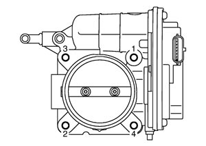 ■ CAUTION ■
- Handle carefully to avoid any shock to electric throttle control actuator.
- Never disassemble and adjust electric throttle control actuator.
- Handle carefully to avoid any shock to electric throttle control actuator.
- The figure shows the electric throttle control actuator (bank 2) viewed from the air duct side.
- Viewed from the air duct side, order of loosening mounting bolts of electric throttle control actuator (bank 2) is the same as that of the electric throttle control actuator (bank 1).
NOTE:
- 5.Remove EVAP canister purge volume control solenoid valve and EVAP tube (front) from intake manifold collector.
- Loosen mounting bolts in reverse order as shown in the figure.
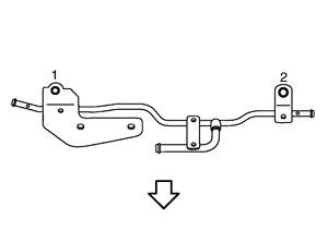

: Engine front
- 6.Remove vacuum hoses, PCV hoses and EVAP hoses, disconnecting each joints
- 7.Remove intake manifold collector.
- Loosen mounting bolts in the reverse order as shown in the figure with power tool.
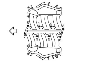
| : Engine front |
■ CAUTION ■
Mark the parts with paint in advance of the reinstallation to prevent misalignment between the intake manifold collector and intake manifold.- 8.Remove balance tube.
- Loosen mounting bolts in the reverse order as shown in the figure with power tool.
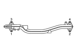
- 9.Remove EVAP tube (bank 1 and bank 2), if necessary.
- 10.Remove water tube and vacuum tube assembly and spacer, if necessary.
- 11.Remove manifold absolute pressure (MAP) sensor, if necessary.
■ CAUTION ■
Handle carefully to avoid any shock to manifold absolute pressure (MAP) sensor. INSTALLATIONNote the following, and install in the reverse order of removal.
 Balance Tube
- Tighten mounting bolts in numerical order as shown in the figure.
: Engine front
Intake Manifold Collector- Tighten mounting bolts in numerical order as shown in the figure.
: Engine front
■ CAUTION ■
- Install each part according to the marks put before removal.
- Tighten mounting bolts with care to avoid misalignment in the intake manifold collector.
- After replacing an intake manifold collector, be sure to adjust the position as instructed below.
- 1.Remove intake manifold. Refer to Exploded View.
■ CAUTION ■
Mark the parts with paint with advance of the reinstallation to prevent misalignment between the intake manifold and cylinder head.- 2.Temporarily assemble intake manifold collector (1) and intake manifold (2).
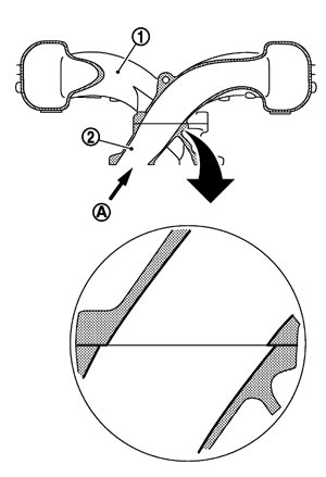
- 3.Check an exact location that the intake manifold collector port locates inside the intake manifold port and mark each part. Refer to the arrow (A) shown in the figure to check the location.
- 4.After another disassembly, install the parts, aligning with the marks put before the temporary assembly.
■ CAUTION ■
Tighten mounting bolts with care to avoid misalignment in the intake manifold collector and intake manifold. Water Hose- Insert hose by 27 to 32 mm (1.06 to 1.26 in) from connector end.
- Clamp hose at location of 3 to 7 mm (0.12 to 0.28 in) from hose end.
Electric Throttle Control Actuator- Tighten bolts in numerical order as shown in the figure.
- Clamp hose at location of 3 to 7 mm (0.12 to 0.28 in) from hose end.NOTE:
- The figure shows the electric throttle control actuator (bank 2) viewed from the air duct side.
- Viewed from the air duct side, the order of tightening mounting bolts of electric throttle control actuator (bank 2) is the same as that of the electric throttle control actuator (bank 1).
- Perform the “Throttle Valve Closed Position Learning” when harness connector of electric throttle control actuator is disconnected. Refer to Description (GT-R certified NISSAN dealer).
- Perform the “Idle Air Volume Learning” and “Throttle Valve Closed Position Learning” when electric throttle control actuator is replaced. Refer to Description (GT-R certified NISSAN dealer) and Description (GT-R certified NISSAN dealer).
- The figure shows the electric throttle control actuator (bank 2) viewed from the air duct side.
Inspection
INSPECTION AFTER REMOVAL Surface Distortion- Check the surface distortion of the intake manifold collector mating surface with a straightedge (A) and a feeler gauge (B).
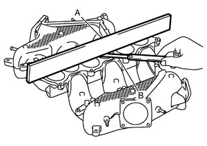
Limit : Refer to Intake Manifold Collector (GT-R certified NISSAN dealer). - If it exceeds the limit, replace intake manifold collector.