CHARGE AIR COOLER
Exploded View
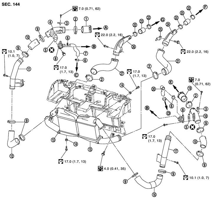
|
1. |
Air inlet hose (bank 1) |
2. |
Clamp |
3. |
Turbocharger boost sensor |
|
4. |
Recirculation pipe (bank 1) |
5. |
Gasket |
6. |
Clamp |
|
7. |
Recirculation hose (bank 1) |
8. |
Recirculation valve |
9. |
Clamp |
|
10. |
Air inlet hose |
11. |
Air inlet pipe assembly (bank 1) |
12. |
Air inlet hose (bank 1) |
|
13. |
Charge air cooler assembly (bank 1) |
14. |
Grommet |
15. |
Charge air cooler assembly (bank 2) |
|
16. |
Air inlet hose (bank 2) |
17. |
Air inlet pipe assembly (bank 2) |
18. |
Recirculation pipe (bank 2) |
|
19. |
Air inlet hose (bank 2) |
20. |
Recirculation hose (bank 2) |
21. |
Air inlet hose (bank 2) |
|
22. |
Clamp |
23. |
Air inlet hose |
24. |
Air inlet pipe (bank 2) |
|
25. |
Bracket |
26. |
Air inlet pipe (bank 1) |
27. |
Air inlet hose (bank 1) |
|
A. |
To electric throttle control actuator (bank 1) |
B. |
To intake manifold collector |
C. |
To exhaust manifold and turbocharger assembly (bank 1) (upper) |
|
D. |
To exhaust manifold and turbocharger assembly (bank 2) (upper) |
E. |
To electric throttle control actuator (bank 2) |
F. |
To exhaust manifold and turbocharger assembly (bank 2) |
|
G. |
To exhaust manifold and turbocharger assembly (bank 1) |
|
|
|
|
|
Refer to Components for symbols in the figure. |
|||||
Removal and Installation
 REMOVAL
- 1.Remove air cleaner case and air duct assembly. Refer to Exploded View.
- 2.Disconnect turbocharger boost sensor harness connector.
- 3.Disconnect air inlet hose to remove the turbocharger boost sensor and the integrated recirculation valve and pipe.
NOTE:
Mark with paint for a reference purpose before removal.- 4.Remove front bumper. Refer to Exploded View.
- 5.Remove air intake duct assembly. Refer to Exploded View (GT-R certified NISSAN dealer).
- 6.Disconnect air inlet hose and pipe to remove the charge air cooler assembly.
■ CAUTION ■
Never damage or scratch charge air cooler core when removing. INSTALLATIONNote the following, and install in the reverse order of removal.
 AIR INLET HOSE ASSEMBLY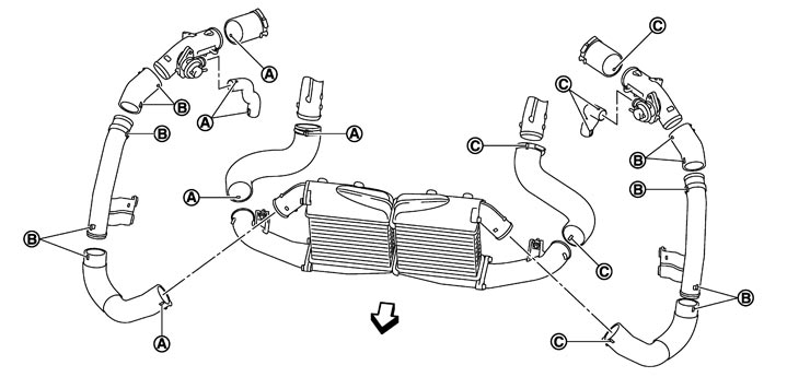
| A. | Matching mark (blue) | B. | Matching mark (yellow) | C. | Matching mark (pink) |
 | : Vehicle front |
- To install each part, refer to the above figure to align the matching marks.
- Temporarily assemble all the removed parts before tightening the clamp.
- Tighten the clamp to the specified torque as shown below:
Clamp tightening torque 
: 4.6 N·m (0.47 kg-m, 41 in-lb)
■ CAUTION ■
Never use air tool or power tools for tightening. AIR INLET PIPE ASSEMBLY- Install air inlet pipe assembly as follows:
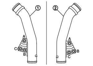
| 1 | : Air inlet pipe assembly (bank 1) |
| 2 | : Air inlet pipe assembly (bank 2) |
- 1.Tighten bolt (A) (temporarily).
- 2.Tighten bolt (B) (temporarily).
- 3.Tighten bolt (C) (specified torque).
- 4.Tighten bolt (A) (specified torque).
- 5.Tighten bolt (B) (specified torque).
Inspection
INSPECTION AFTER REMOVAL Recirculation Valve- Check that diaphragm lifts and the valve (B) opens when applying negative pressure with a handy vacuum pump (commercial service tool) (A).
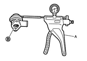
Standard : Refer to Recirculation Valve (GT-R certified NISSAN dealer). - If it exceeds the standard, replace recirculation valve.
Checking Charge Air Cooler- Visually check that there is no incident and damage on the charge air cooler core and air tank (upper side and lower side).
- If there is an unusual condition, replace the charge air cooler.
Cleaning Charge Air CoolerCheck charge air cooler for mud or clogging. If necessary, clean charge air cooler as follows:
■ CAUTION ■
- Be careful not to bend or damage the charge air cooler fins.
- When charge air cooler is cleaned without removal, remove all surrounding parts such as cooling fan shroud and horns. Then tape the harness and connectors to prevent water from entering.
- 1.Apply water by hose to the back side of the charge air cooler core vertically download.
- Apply water again to all charge air cooler core surfaces once per minute.
- Stop washing if any stains no longer flow out from the charge air cooler.
- 2.Blow air into the back side of charge air cooler core vertically download.
- Use compressed air lower than 490 kPa (4.9 bar, 5 kg/cm2, 71 psi) and keep distance more than 30 cm (11.81 in).
- Blow air again into all the charge air cooler core surfaces once per minute until no water sprays out.