EXHAUST MANIFOLD AND TURBOCHARGER ASSEMBLY
Exploded View
Bank 1 side
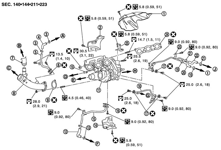
|
1. |
Exhaust manifold cover |
2. |
Insulator (upper) |
3. |
Clamp |
|
4. |
Fresh air hose |
5. |
Fresh air tube |
6. |
Gasket |
|
7. |
Recirculation hose |
8. |
Air inlet pipe |
9. |
Gasket |
|
10. |
Vacuum hose |
11. |
Exhaust manifold and turbocharger assembly |
12. |
Oil return hose |
|
13. |
Clamp |
14. |
Insulator (lower) |
15. |
Oil return tube |
|
16. |
Gasket |
17. |
Gasket |
18. |
Water inlet tube |
|
19. |
Clamp |
20. |
Water hose |
21. |
Clamp |
|
22. |
Water hose |
23. |
Water outlet tube |
24. |
Gasket |
|
25. |
Bracket |
|
|
|
|
|
A. |
To rocker cover (bank 1) |
B. |
To recirculation valve (bank 1) |
C. |
To air cleaner (bank 1) |
|
D. |
To turbocharger boost control solenoid valve |
E. |
To charge air cooler |
F. |
To oil filter bracket |
|
G. |
To cylinder block |
H. |
To three way catalyst (bank 1) |
I. |
To heater pipe |
|
J. |
To air cut solenoid valve (bank 2) |
|
|
|
|
|
Refer to Components for symbols in the figure. |
|||||
Bank 2 side
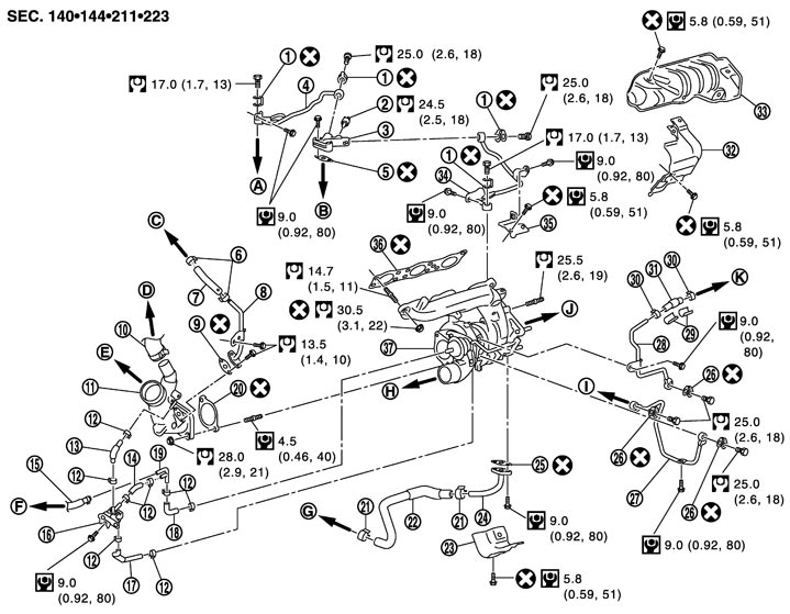
|
1. |
Gasket |
2. |
Oil temperature sensor |
3. |
Oil feed adapter |
|
4. |
Oil feed tube (bank 1) |
5. |
Gasket |
6. |
Clamp |
|
7. |
Fresh air hose |
8. |
Fresh air tube |
9. |
Gasket |
|
10. |
Recirculation hose |
11. |
Air inlet pipe |
12. |
Clamp |
|
13. |
Vacuum hose |
14. |
Vacuum hose |
15. |
Vacuum hose |
|
16. |
Turbocharger boost control solenoid valve |
17. |
Vacuum hose |
18. |
Vacuum hose |
|
19. |
3- WAY connector |
20. |
Gasket |
21. |
Clamp |
|
22. |
Oil return hose |
23. |
Insulator (lower) |
24. |
Oil return tube |
|
25. |
Gasket |
26. |
Gasket |
27. |
Water inlet tube |
|
28. |
Water outlet tube |
29. |
Clip |
30. |
Clamp |
|
31. |
Water hose |
32. |
Insulator (upper) |
33. |
Exhaust manifold cover |
|
34. |
Oil feed tube |
35. |
Bracket |
36. |
Gasket |
|
37. |
Exhaust manifold and turbocharger assembly |
|
|
|
|
|
A. |
To exhaust manifold and turbocharger assembly (bank 1) |
B. |
To cylinder block |
C. |
To rocker cover (bank 2) |
|
D. |
To recirculation valve (bank 2) |
E. |
To air cleaner (bank 2) |
F. |
To exhaust manifold and turbocharger assembly (bank 1) |
|
G. |
To oil pan (upper) |
H. |
To charge air cooler |
I. |
To cylinder block |
|
J. |
To three way catalyst (bank 2) |
K. |
To heater pipe |
|
|
|
Refer to Components for symbols in the figure. |
|||||
Disassembly and Assembly
 DISASSEMBLY
- 1.Remove air inlet pipe, fresh air hose and fresh air tube.
- 2.Remove turbocharger boost control solenoid valve.
■ CAUTION ■
Never shock turbocharger boost control solenoid valve.- 3.Remove insulator (upper and lower).
- 4.Remove water inlet tube and water outlet tube.
- 5.Remove oil feed tube and oil return tube.
- 6.Remove exhaust manifold and turbocharger assembly as follows:
- Be careful not to bend piping.
- Never hold actuator rod.
- Check the following route if compressor wheel, turbine wheel, and/or rotor shaft were broken. Remove all fragments and other foreign materials in order to avoid secondary contamination.
-
(1)Loosen mounting nuts in the reverse order as shown in the figure.
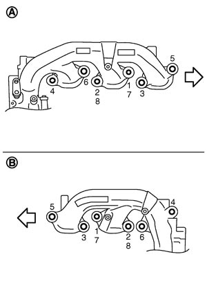
| A | : Bank 1 |
| B | : Bank 2 |
 | : Engine front |
■ CAUTION ■
Disregard the numerical order No. 7 and 8 in removal.NOTE:
Apply penetrating lubricant to nuts before operation.-
(2)Remove exhaust manifold and turbocharger assembly.
■ CAUTION ■
| Intake side: | Between exhaust manifold and turbocharger assembly and charge air cooler |
| Between exhaust manifold and turbocharger assembly and air cleaner | |
| Exhaust side: | |
| Between exhaust manifold and turbocharger assembly and three way catalyst |
ASSEMBLYNote the following, and install in the reverse order of removal.
 Exhaust manifold and Turbocharger Assembly Gasket
- To install, check that the identification hole (triangle mark) (C) is located as shown in the figure.
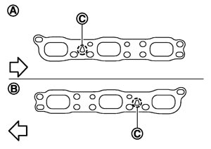
A : Bank 1 B : Bank 2 : Engine front
Exhaust manifold and Turbocharger Assembly- Tighten mounting nuts in numerical order as shown in the figure.
A : Bank 1 B : Bank 2 : Engine front
NOTE:
Tighten nuts No. 1 and 2 in two steps. The numerical order No. 7 and 8 shows second step. Water Inlet Tube and Water Outlet Tube- After temporarily installing each part, check for a twist or bent, and tighten mounting bolts.■ CAUTION ■Be careful not to bend piping.
Oil Feed Tube and Oil Return Tube- After temporarily installing each part, check for a twist or bent, and tighten mounting bolts of the feed side.■ CAUTION ■Be careful not to bend piping.
Inspection
INSPECTION PROCEDURE Trouble Diagnosis of TurbochargerCheck items before trouble diagnosis
- 1.Check that the engine oil level is between L (Low level) and H (High level) of the oil level gauge. [When the engine oil amount is more then H (High level), the engine oil flows into the inlet duct through the blow‐by gas passage, and the turbocharger is misjudged failure.] Refer to Inspection.
- 2.Ask the customer if he/she always runs the vehicle in idle engine speed to cool the engine oil down after driving.
- Replace the exhaust manifold and turbocharger assembly when any malfunction is found after unit inspections specified in the table below.
- If no malfunction is found after the unit inspections, judge that the turbocharger body has no non‐standard conditions. Check the other parts again.
Inspection Location Result Symptoms likely to occur when the results shown on the left exist. Oil leakage Smoke Noise Poor power
Poor accelerationTurbine wheel Wet with oil. C A C C Carbon deposits observed. C A B B “Rubs against” housing. C B A B Vane is bent or broken. A A Compressor wheel Inside of intake port is badly stained with oil. B B “Rubs against” housing. C B A B Vane is bent or broken. A A Check both turbine and compressor rotor shaft end play. Heavy feel or catching when turned by hand. C C B Cannot be turned by hand. A Excessively loose bearing. C C B C Rotor shaft, oil return port (Check inside using penlight.) Carbon or sludge deposits in oil drain port. C A C C Boost control valve actuator operation (using a handy pump) - Does not operate smoothly when air pressure is gradually applied.
- Stroke amount is not compliance with the air pressure.
A A: Highly possible. B: Possible. C: May exist. - Does not operate smoothly when air pressure is gradually applied.
INSPECTION AFTER DISASSEMBLY- Check for the following items and clean the parts if there are adherents. When finding a malfunction or disagreement with the standard value, replace exhaust manifold and turbocharger assembly.
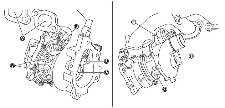
|
A. |
Check for exhaust gas leakage |
B. |
Check for water leakage |
C. |
Check for compressor wheel and rotor shaft |
|
D. |
Check for boost control valve |
E. |
Check for oil leakage |
F. |
Check for boost pressure control |
|
G. |
Check for oil leakage |
H. |
Check for turbine wheel and rotor shaft |
|
|
- Refer to the figure for component names and visually check points.
Cleaning Procedure- Clean the oil feed and the return port with engine conditioner.
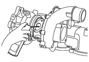
- Clean the water inlet and the outlet port with radiator cleaner.
- Dry it using an air gun (A) after cleaning.
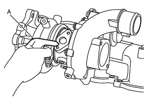
- Dry compressor wheel, turbine wheel, compressor housing, and turbine housing using an air gun.
Surface Distortion- Use a reliable straightedge (A) and feeler gauge (B) to check the flatness of exhaust manifold and turbocharger assembly fitting surface.
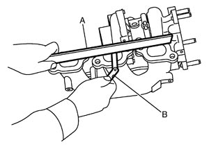
Limit : Refer to Exhaust Manifold And Turbocharger.
Turbine Wheel and Boost Control Valve- Check that the boost control valve (A) has no deformation and cracks.
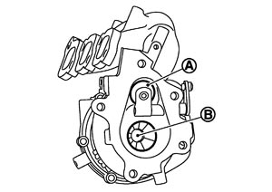
- Check for engine oil stains on turbine wheel (B).
- Check for carbon deposits.
- Check if turbine wheel vane is bent or broken.
- Check for interference with turbine housing.
Compressor Wheel- Check for engine oil stains inside inlet port.
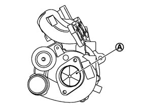
- Check if compressor wheel (A) is bent or broken.
- Check for interference with compressor housing.
Rotor Shaft- Check that the rotor shaft (A) rotates smoothly without any resistance when it is rotated by fingertips.
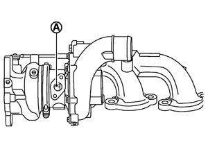
- Shake rotor shaft vertically and horizontally and check for looseness.
- Check for carbon sludge deposits.
Rotor Shaft End Play- Place a dial indicator (B) at the rotor shaft end (A) in the axial direction to measure the end play.
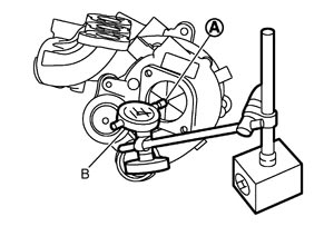
Standard : 0.031 - 0.099 mm (0.0012 - 0.0039 in)
Boost Control- Check that actuator rod activates and boost control valve opens when applying pressure with a pressurized handy pump (commercial service tool) (B).
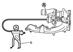 ■ CAUTION ■Never apply a pressure of 70 kPa (525 mmHg, 20.7 inHg) or more to prevent a diaphragm in the boost control actuator (A) from damage.
 - Check that the boost control valve is in absolute contact with the turbine housing without an inspection pressure.
Standard: Pressure/Actuator rod distance (stroke) Bank 1 : 61.4 kPa (460 mmHg, 18.1 inHg)/1.0 mm (0.039 in) Bank 2 : 56.4 kPa (423 mmHg, 16.7 inHg)/1.0 mm (0.039 in)
Oil Feed Tube and Oil Return Tube- Clean inside of oil feed tube and oil return tube, and check tubes for clogging.
Water Inlet Tube and Water Outlet Tube- Clean inside of water inlet tube and water outlet tube, and check tubes for clogging.
INSPECTION AFTER ASSEMBLYStart engine, and raise engine speed to check that there are exhaust gas and no oil leakage.