FUEL INJECTOR AND FUEL TUBE
Exploded View
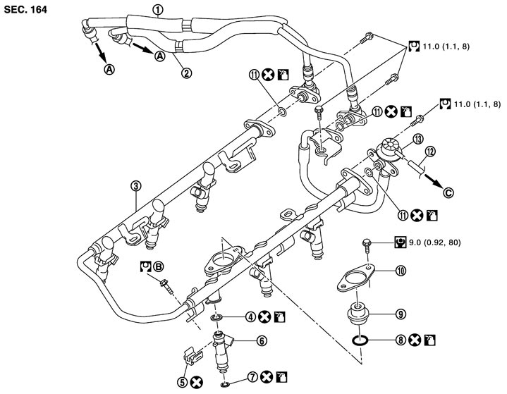
|
1. |
Fuel feed hose (with damper) |
2. |
Fuel return hose (with damper) |
3. |
Fuel tube |
|
4. |
O-ring (black) |
5. |
Clip |
6. |
Fuel injector |
|
7. |
O-ring (green) |
8. |
O‐ring |
9. |
Fuel damper |
|
10. |
Fuel damper cap |
11. |
O‐ring |
12. |
Vacuum hose |
|
13. |
Fuel hose (with pressure regulator) |
|
|
|
|
|
A. |
To centralized under-floor piping |
B. |
Refer to Removal and Installation (GT-R certified NISSAN dealer) |
C. |
To intake manifold collector |
|
Refer to Components for symbols in the figure. |
|||||
■ CAUTION ■
Never remove or disassemble parts unless instructed as shown in the figure.
Removal and Installation
 REMOVAL
■ WARNING ■
- Put a “CAUTION: FLAMMABLE” sign in the workshop.
- Be sure to work in a well ventilated area and furnish workshop with a CO2 fire extinguisher.
- Never smoke while servicing fuel system. Keep open flames and sparks away from the work area.
- To avoid the danger of being scalded, never drain engine coolant when the engine is hot.
- 1.Release fuel pressure. Refer to Inspection.
- 2.Remove engine cover with power tool. Refer to Exploded View.
- 3.Disconnect fuel feed hose (with damper) (1) and fuel return hose (with damper) (2) from centralized under-floor piping connection, disconnect quick connector as follows:
- Keep parts away from heat source. Especially, be careful when welding is performed around them.
- Never expose parts to battery electrolyte or other acids.
- Never pull with lateral force applied. O-ring inside quick connector may be damaged.
- Never remove the remaining retainer.
- Never bend or twist connection between quick connector and fuel hose during installation/removal.
- When centralized under-floor piping is replaced, also replace retainer with a new one.
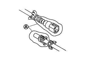
Retainer color Feed side : Yellow Return side : Light blue - To keep clean the connecting portion and to avoid damage and foreign materials, cover them completely with plastic bags, etc. (A) or something similar.
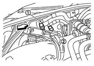
 | : Engine front |
-
(1)Push in retainer (D).
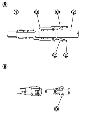
| 1 | : Fuel hose |
| A | : Connection (Cross-section) |
| C | : Tabs |
| E | : Disconnection |
-
(2)Draw and pull out quick connector (B) straight from centralized under-floor piping (2).
■ CAUTION ■
- 4.Remove intake manifold collector. Refer to Exploded View.
■ CAUTION ■
Mark the parts with paint in advance of the reinstallation to prevent misalignment between the intake manifold collector and intake manifold.- 5.Remove fuel feed hose (with damper) and fuel return hose (with damper) from fuel tube.
- 6.Remove fuel hose (with pressure regulator), if necessary.
■ CAUTION ■
Never tilt it, or remaining fuel in pipes may flow out from pipes.- 7.Disconnect fuel injector sub harness from fuel injector.
- 8.Remove fuel tube and fuel injector assembly.
- Loosen mounting bolts in reverse order as shown in the figure.
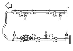
| : Engine front |
■ CAUTION ■
Never tilt it, or remaining fuel in pipes may flow out from pipes.- 9.Remove fuel injector from fuel tube (1) as follows:
- Be careful with remaining fuel that may go out from fuel tube.
- Be careful not to damage injector nozzles during removal.
- Never bump or drop fuel injector.
- Never disassemble fuel injector.
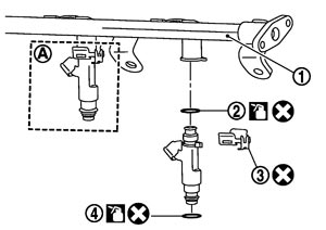
| 2 | : O‐ring (black) |
| 4 | : O‐ring (green) |
| A | : Installed condition |
-
(1)Open and remove clip (3).
-
(2)Remove fuel injector from fuel tube by pulling straight.
■ CAUTION ■
- 10.Remove fuel damper from fuel tube, if necessary.
INSTALLATION- 1.Install fuel damper (2) as follows:
- Handle O‐ring with bare hands. Never wear gloves.
- Lubricate O‐ring with new engine oil.
- Never clean O‐ring with solvent.
- Check that O‐ring and its mating part are free of foreign material.
- When installing O‐ring, be careful not to scratch it with tool or fingernails. Also be careful not to twist or stretch O‐ring. If O‐ring was stretched while it was being attached, never insert it quickly into fuel tube.
- Insert new O‐ring straight into fuel tube. Never twist it.
- Insert fuel damper until (A) is touching (B) of fuel tube.
- Insert straight, making sure that the axis is lined up.
- Never pressure‐fit with excessive force.
Reference value : 130 N (13.3 kg, 29.2 lb) - After tightening bolts, check that there is no gap between fuel damper cap and fuel tube.
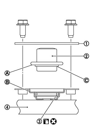
| 1 | : Fuel damper cap |
-
(1)Install new O‐ring (3) to fuel tube (4) as shown. When handling new O‐ring, be careful of the following caution:
■ CAUTION ■
-
(2)Install spacer (C) to fuel damper.
-
(3)Insert fuel damper straight into fuel tube.
■ CAUTION ■
-
(4)Tighten bolts evenly in turn.
- 2.Install new O-rings to fuel injector, paying attention to the following.
- Upper and lower O-ring are different. Be careful not to confuse them.
Fuel tube side : Black Nozzle side : Green - Handle O-ring with bare hands. Never wear gloves.
- Lubricate O-ring with new engine oil.
- Never clean O-ring with solvent.
- Check that O-ring and its mating part are free of foreign material.
- When installing O-ring, be careful not to scratch it with tool or fingernails. Also be careful not to twist or stretch O-ring. If O-ring was stretched while it was being attached, never insert it quickly into fuel tube.
- Insert O-ring straight into fuel injector. Never decenter or twist it.
■ CAUTION ■
- 3.Install fuel injector (4) to fuel tube as follows:
- Insert clip so that protrusion (D) of fuel injector matches cutout (F) of clip.
- Never reuse clip. Replace it with a new one.
- Be careful to keep clip from interfering with O-ring. If interference occurs, replace O-ring.
- Insert it while matching it to the axial center.
- Insert fuel injector so that protrusion (B) of fuel tube matches cutout (G) of clip.
- Check that fuel tube flange (A) is securely fixed in flange fixing groove (E) on clip.■ CAUTION ■Never pressure‐fit with excessive force.
Reference value : 130 N (13.3 kg, 29.2 lb) - Check that protrusions of fuel injectors are aligned with cutouts of clips after installation.
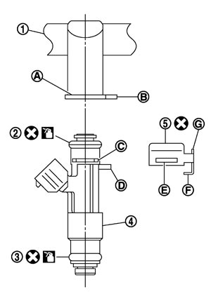
| 2 | : O‐ring (Black) |
| 3 | : O‐ring (Green) |
-
(1)Insert clip (5) into clip mounting groove (C) on fuel injector.
■ CAUTION ■
-
(2)Insert fuel injector into fuel tube (1) with clip attached.
-
(3)Check that installation is complete by checking that fuel injector does not rotate or come off.
- 4.Install fuel tube and fuel injector assembly.
- Tighten mounting bolts in two steps in numerical order as shown in the figure.
: Engine front  1st step
: 10.1 N·m (1.0 kg-m, 7 ft-lb) 2nd step: 22.0 N·m (2.2 kg-m, 16 ft-lb)
■ CAUTION ■
Be careful not to let tip of injector nozzle come in contact with other parts.- 5.Connect fuel injector sub harness.
- 6.Install fuel hose (with pressure regulator), if removed.
- Handling procedure of O‐ring is the same as that of fuel damper.
- Insert fuel damper straight into fuel tube.
- Tighten mounting bolts evenly in turn.
- After tightening mounting bolts, check that there is no gap between flange and fuel tube.
- 7.Install fuel feed hose (with damper) and fuel return hose (with damper) as follows:
- Handling procedure of O‐ring is the same as that of fuel damper.
- Insert fuel damper straight into fuel tube.
- Tighten mounting bolts evenly in turn.
- After tightening mounting bolts, check that there is no gap between flange and fuel tube.
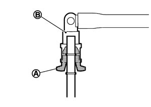
- Visually confirm that the two retainer tabs (A) are connected to the quick connector (B).
- Carefully align center to avoid inclined insertion to prevent damage to O-ring inside quick connector.
- Insert until you hear a “click” sound and actually feel the engagement.
- To avoid misidentification of engagement with a similar sound, be sure to perform the next step.
-
(1)Fuel tube side:
-
(2)Connect quick connector centralized under-floor piping side:
- 1)Check no foreign substances are deposited in and around centralized under-floor piping and quick connector, and no damage on them.
- 2)Thinly apply new engine oil around centralized under-floor piping from tip end to spool end.
- 3)Align center to insert quick connector straightly into centralized under-floor piping.
■ CAUTION ■
- 4)Pull quick connector (A) by hand holding position. Check it is completely engaged (connected) so that it does not come out from fuel piping.
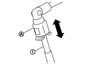
| 1 | : Centralized under-floor piping |
- 8.Install in the reverse order of removal after this step.
Inspection
INSPECTION AFTER INSTALLATION Check on Fuel Leakage
- 1.Turn ignition switch “ON” (with the engine stopped). With fuel pressure applied to fuel piping, check there are no fuel leaks at connection points.
NOTE:
Use mirrors for checking at points out of clear sight.- 2.Start the engine. With engine speed increased, check again that there are no fuel leaks at connection points.
■ CAUTION ■
Never touch the engine immediately after stopped, as the engine becomes extremely hot.