IGNITION COIL, SPARK PLUG AND ROCKER COVER
Exploded View
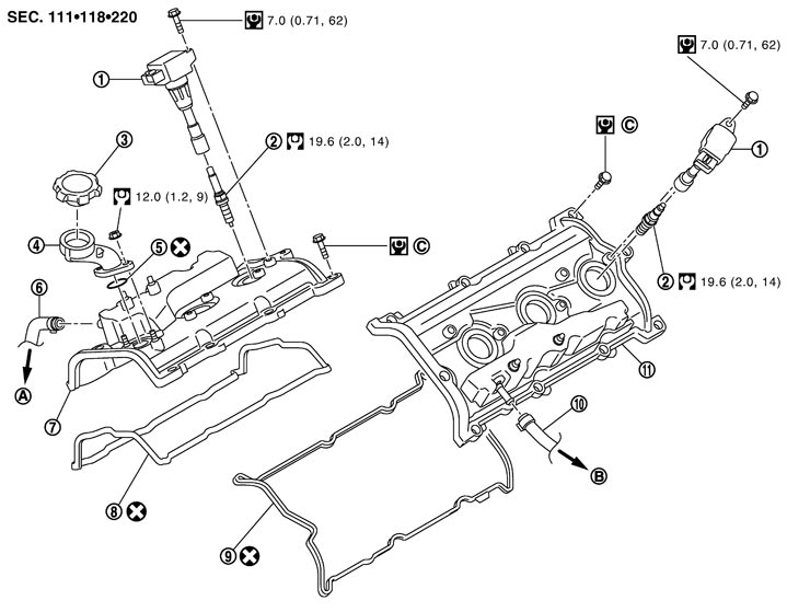
|
1. |
Ignition coil |
2. |
Spark plug |
3. |
Oil filler cap |
|
4. |
Oil filler tube |
5. |
O-ring |
6. |
Fresh air hose |
|
7. |
Rocker cover (bank 1) |
8. |
Rocker cover gasket (bank 1) |
9. |
Rocker cover gasket (bank 2) |
|
10. |
Fresh air hose |
11. |
Rocker cover (bank 2) |
|
|
|
A. |
To fresh air tube (bank 1) |
B. |
To fresh air tube (bank 2) |
C. |
Refer to Removal and Installation (GT-R certified NISSAN dealer) |
|
Refer to Components for symbols in the figure. |
|||||
Removal and Installation
 REMOVAL
- 1.Remove engine cover. Refer to Exploded View.
- 2.Remove intake manifold collector. Refer to Exploded View.
■ CAUTION ■
Mark the parts with paint in advance of the reinstallation to prevent misalignment between the intake manifold collector and intake manifold.- 3.Disconnect EVAP tube. Refer to Exploded View.
- 4.Remove ignition coil.
■ CAUTION ■
Never shock ignition coil.- 5.Remove fresh air hose.
- 6.Loosen heater pipe mounting bolts (bank 2 side). Refer to Exploded View (GT-R certified NISSAN dealer).
- 7.Remove rocker cover.
- Loosen bolts in reverse order shown in the figure.
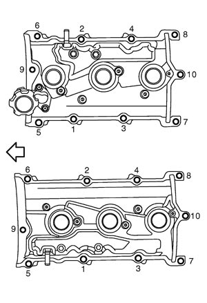
 | : Engine front |
- 8.Remove rocker cover gasket from rocker cover.
- 9.Remove oil filler tube from rocker cover, if necessary.
- 10.Use scraper to remove all traces of liquid gasket from cylinder head and camshaft bracket (No. 1).
■ CAUTION ■
Never scratch or damage the mating surface when cleaning off old liquid gasket. INSTALLATION- 1.Apply liquid gasket to camshaft bracket (No. 1) (1) and camshaft sensor bracket (2). (bank 1 and bank 2)
- Apply liquid gasket on the front and rear side of engine first. [5 mm (0.20 in) + 5 mm (0.20 in) side as shown in the figure]
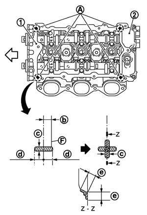
| A | : Liquid gasket application point |
| F | : End surface of camshaft bracket (No. 1) |
| b | : 4 mm (0.16 in) |
| c | : φ2.5 - 3.5 mm (0.098 - 0.138 in) |
| d | : 5 mm (0.20 in) |
| e | : 10 mm (0.39 in) |
| : Engine front |
Use Genuine RTV silicone sealant or equivalent. Refer toRecommended Chemical Products and Sealants.
NOTE:
The figure shows an example of bank 1 side.- 2.Install rocker cover as follows:
- Check if rocker cover gasket is not dropped from the installation groove of rocker cover.
-
(1)Install rocker cover gasket to rocker cover.
-
(2)Tighten bolts in two steps separately in numerical order as shown in the figure.
| : Engine front |
 1st step 1st step | : 2.0 N·m (0.2 kg‐m, 18 in-lb) |
| 2nd step | : 8.3 N·m (0.85 kg‐m, 73 in-lb) |
- 3.
- 4.Install fresh air hose.
- Insert hose by 27 to 32 mm (1.06 to 1.26 in) from connector end.
- 5.Install in the reverse order of removal after this step.