TIMING CHAIN
Exploded View
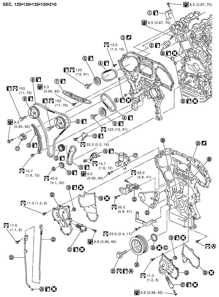
|
1. |
Timing chain tensioner (secondary) (bank 1) |
2. |
Timing chain tensioner (secondary) (bank 2) |
3. |
Rear timing chain case |
|
4. |
Timing chain (secondary) |
5. |
Camshaft sprocket (EXH) |
6. |
O-ring |
|
7. |
Internal chain guide |
8. |
Timing chain (primary) |
9. |
Camshaft sprocket (INT) |
|
10. |
Slack guide |
11. |
Timing chain tensioner (primary) |
12. |
Crankshaft sprocket |
|
13. |
Tension guide |
14. |
Oil pump sprocket |
15. |
Oil pump drive chain |
|
16. |
Oil pump drive chain tensioner |
17. |
Water outlet (front) |
18. |
Gasket |
|
19. |
Rubber ring |
20. |
Intake valve timing control cover (bank 1) |
21. |
Intake valve timing control solenoid valve (bank 1) |
|
22. |
Oil level gauge |
23. |
Oil level gauge guide |
24. |
O-ring |
|
25. |
Crankshaft pulley bolt |
26. |
Crankshaft pulley |
27. |
Intake valve timing control solenoid valve (bank 2) |
|
28. |
Intake valve timing control cover (bank 2) |
29. |
Gasket |
30. |
Front oil seal |
|
31. |
Alternator bracket |
32. |
Power steering oil pump bracket |
33. |
Idler pulley bracket |
|
34. |
Front timing chain case |
35. |
O-ring |
36. |
O-ring |
|
A. |
Refer to Disassembly and Assembly (GT-R certified NISSAN dealer) |
B. |
Oil filter |
C. |
Apply neutral detergent on the rim |
|
Refer to Components for symbols in the figure. |
|||||
Disassembly and Assembly
 DISASSEMBLY
- 1.Remove intake manifold collector. Refer to Exploded View.
■ CAUTION ■
Mark the parts with paint in advance of the reinstallation to prevent misalignment between the intake manifold collector and intake manifold.- 2.Remove oil level gauge and oil level gauge guide.
- 3.Remove power steering oil pump bracket.
- 4.Remove alternator bracket.
- 5.Remove idler pulley bracket.
- 6.Remove water outlet (front) and heater pipe. Refer to Exploded View (GT-R certified NISSAN dealer).
- 7.Remove intake valve timing control covers as follows:
-
(1)Disconnect intake valve timing control solenoid valve harness connector.
-
(2)Loosen mounting bolts in reverse order as shown in the figure.
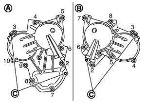
| A | : Bank 1 |
| B | : Bank 2 |
| C | : Dowel pin hole |
-
(3)Shaft is engaged with camshaft sprocket (INT) center hole on inside. Pull straight out so that it does not tilt until the joint is disengaged.
■ CAUTION ■
Never shock intake valve timing control cover.- 8.Remove intake valve timing control solenoid valve, if necessary.
■ CAUTION ■
Intake valve timing control solenoid valve is nonreusable. Never remove it unless required.- 9.Remove rocker cover. Refer to Exploded View.
- 10.Obtain No. 1 cylinder at TDC of its compression stroke as follows:
- If not, turn crankshaft one revolution (360 degrees) and align as shown in the figure.
-
(1)Rotate crankshaft pulley clockwise to align timing mark (grooved line without color) with timing indicator (1).
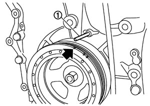
 | : Timing mark (grooved line without color) |
NOTE:
Timing indicator is not included because it is not factory-supplied.-
(2)Check that intake and exhaust cam noses on No. 1 cylinder (engine front side of bank 1) are located as shown in the figure.
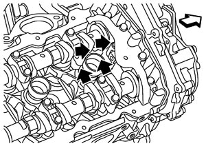
 | : Engine front |
- 11.Remove crankshaft pulley. Refer to Setting (GT-R certified NISSAN dealer) for the removing procedure.
- 12.Remove front timing chain case as follows:
- Never use a screwdriver or something similar.
- After removal, handle front timing chain case carefully so it does not tilt, cant, or warp under a load.
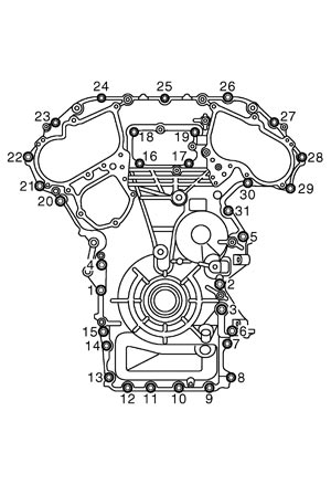
-
(1)Loosen mounting bolts in reverse order as shown in the figure.
-
(2)Insert a suitable tool (A) into the notch at the top of front timing chain case as shown.
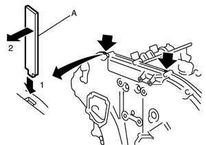
-
(3)Pry off case by moving the suitable tool as shown.
■ CAUTION ■
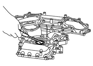
- 13.Remove front oil seal from front timing chain case using a suitable tool.
- Use a screwdriver for removal.
■ CAUTION ■
Be careful not to damage front timing chain case.- 14.Remove O-rings (1).
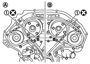
| A | : Bank 1 |
| B | : Bank 2 |
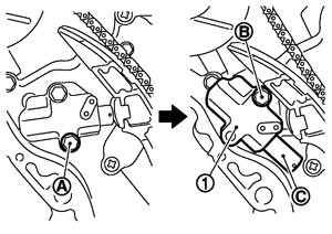
- 15.Remove timing chain tensioner (primary) (1) as follows:
-
(1)Remove lower mounting bolt (A).
-
(2)Loosen upper mounting bolt (B) slowly, and then turn timing chain tensioner (primary) on the upper mounting bolt so that plunger (C) is fully expanded.
NOTE:
Even if plunger is fully expanded, it is not dropped from the body of timing chain tensioner (primary).-
(3)Remove upper mounting bolt, and then remove timing chain tensioner (primary).
■ CAUTION ■
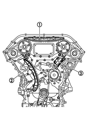
After removing timing chain tensioner (primary), never turn crankshaft and camshaft separately, or valves will strike the piston heads.- 16.Remove internal chain guide (1), slack guide (2) and tension guide (3).
- 17.Remove timing chain (primary).
- 18.Remove timing chain (secondary) and camshaft sprockets as follows:
- Secure the hexagonal portion of camshaft using a wrench to loosen mounting bolts.
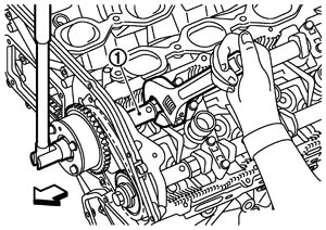
1 : Camshaft (INT) : Engine front - Never loosen the mounting bolts with securing anything other than the camshaft hexagonal portion or with tensioning the timing chain.
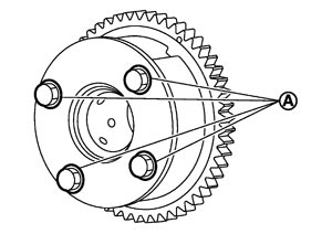
- Never disassemble camshaft sprocket (INT). [Never loosen bolts (A) as shown in the figure.]
-
(1)Attach suitable stopper pin (C) to the right and left timing chain tensioners (secondary) (1), (2).
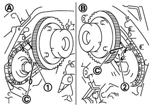
| A | : Bank 1 |
| B | : Bank 2 |
NOTE:
Use approximately 0.5 mm (0.02 in) dia. hard metal pin as a stopper pin.-
(2)Remove camshaft sprocket mounting bolts (INT and EXH).
■ CAUTION ■
-
(3)Remove timing chain (secondary) together with camshaft sprockets.
- 19.Remove the crankshaft sprocket and the oil pump related parts as follows:
- Pull out spring (B) from spring fixing hole (A).
-
(1)Remove oil pump drive chain tensioner (1).
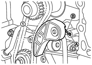
NOTE:
At this step, the tensioner does not have to be fixed to release tension.-
(2)Hold the hexagonal portion of oil pump sprocket, and then loosen the oil pump sprocket mounting nut.
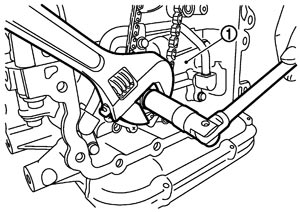
| 1 | : Oil pump assembly |
NOTE:
There is no matching mark in the oil pump related parts.-
(3)Remove the crankshaft sprocket, the oil pump drive chain, and the oil pump sprocket at the same time.
- 20.Remove water pump. Refer to Exploded View (GT-R certified NISSAN dealer).
- 21.Remove oil pan (upper). Refer to Exploded View (GT-R certified NISSAN dealer).
- 22.Remove rear timing chain case as follows:
- Never remove plate metal cover (A) of oil passage.
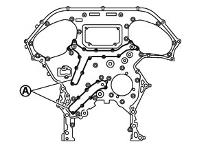
- After removal, handle rear timing chain case carefully so it does not tilt, cant, or warp under a load.
-
(1)Loosen mounting bolts in reverse order as shown in the figure.
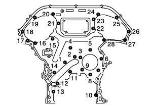
-
(2)Cut liquid gasket using the seal cutter [SST: KV10111100 (J37228)] and remove rear timing chain case.
■ CAUTION ■
- 23.Remove O-rings (1).
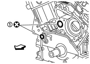
| : Engine front |
- 24.Remove timing chain tensioners (secondary) from cylinder head as follows, if necessary.
-
(1)Remove camshaft brackets (No. 1). Refer to Exploded View (GT-R certified NISSAN dealer).
-
(2)Remove timing chain tensioners (secondary) with a stopper pin attached.
ASSEMBLYNOTE:
The below figure shows the relationship between the matching mark on each timing chain and that on the corresponding sprocket, with the components installed.
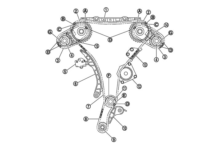
|
1. |
Internal chain guide |
2. |
Camshaft sprocket (INT) |
3. |
Timing chain (secondary) |
|
4. |
Camshaft sprocket (EXH) |
5. |
Timing chain tensioner (primary) |
6. |
Slack guide |
|
7. |
Timing chain (primary) |
8. |
Oil pump drive chain |
9. |
Oil pump sprocket |
|
10. |
Oil pump drive chain tensioner |
11. |
Crankshaft sprocket |
12. |
Water pump |
|
13. |
Tension guide |
14. |
Timing chain tensioner (secondary) (bank 2) |
15. |
Timing chain tensioner (secondary) (bank 1) |
|
A. |
Matching mark [punched (back side)] |
B. |
Matching mark (yellow link) |
C. |
Matching mark (punched) |
|
D. |
Matching mark (orange link) |
E. |
Matching mark (notched) |
F. |
Crankshaft key |
|
G. |
Matching mark (punched) |
|
|
|
|
- 1.Install timing chain tensioners (secondary) to cylinder head, if removed. Refer to Exploded View (GT-R certified NISSAN dealer).
- 2.Install rear timing chain case as follows:
- For in the figure, completely wipe off liquid gasket extended on a portion touching at engine coolant.
- Apply liquid gasket on installation position of water pump and cylinder head completely.
- Check that O-rings stay in place during installation to cylinder block.
- If liquid gasket protrudes, wipe it off immediately.
- If not within the standard, repeat the installation procedure.
-
(1)Install O-rings (1).
| : Engine front |
-
(2)Apply liquid gasket with the cartridge gun (commercial service tool) to rear timing chain case back side as shown in the figure.Use Genuine RTV Silicone Sealant or equivalent. Refer to Recommended Chemical Products and Sealants.
■ CAUTION ■
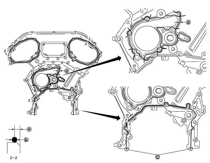
| a. | 4.8 mm (0.189 in) | b. | φ3.9 mm (0.154 in) | c. | Protrusions at beginning and end of gasket |
| d. | φ2.7 mm (0.106 in) |
-
(3)Align rear timing chain case with dowel pins on cylinder block and install rear timing chain case.
-
(4)Tighten mounting bolts in numerical order as shown in the figure.
| Bolt length | |
| 20 mm (0.79 in) | : 1, 2, 3, 4, 5, 6, 7, 8, 9 |
| 16 mm (0.63 in) | : Except the above |
-
(5)After all bolts are tightened, retighten them to the specified torque in numerical order shown in the figure.
-
(6)After installing rear timing chain case, check the surface height difference between the following parts on the oil pan (upper) mounting surface.
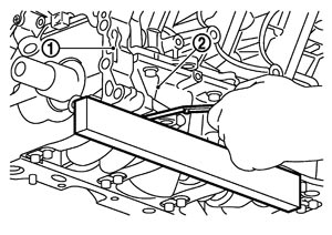
| 1 | : Rear timing chain case |
| 2 | : Lower cylinder block |
| Standard | : Less than –0.24 mm (–0.0094 in) |
- 3.Install water pump. Refer to Exploded View (GT-R certified NISSAN dealer).
- 4.Check that dowel pin (A) and crankshaft key (1) are located as shown in the figure. (No. 1 cylinder at compression TDC)
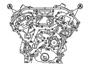
NOTE:
Though camshaft does not stop at the position as shown in the figure, for the placement of cam noses, it is generally accepted camshaft is placed for the same direction of the figure.| Camshaft dowel pin | |
| : At cylinder head upper face side in each bank | |
| Crankshaft key | |
| : At cylinder head side of bank 1 | |
- 5.Install timing chains (secondary) and camshaft sprockets as follows:
- Align the matching marks on timing chain (secondary) (orange link) with the ones on intake and exhaust camshaft sprockets (punched), and install them.NOTE:
- Figure shows bank 1 (rear view).
- Matching marks for camshaft sprockets (INT) are on the back side of camshaft sprockets (secondary).
- There are two types of matching marks, circle and oval types. They should be used for the bank 1 and bank 2, respectively.
Bank 1 : Use circle type Bank 2 : Use oval type
- Figure shows bank 1 (rear view).
- Align dowel pin camshafts with the groove on sprockets, and install them.
- In case that positions of each matching mark and each dowel pin are not fit on matching parts, make fine adjustment to the position holding the hexagonal portion on camshaft with wrench or equivalent.
- Mounting bolts for camshaft sprockets must be tightened in the next step. Tightening them by hand is enough to prevent the dislocation of dowel pins.
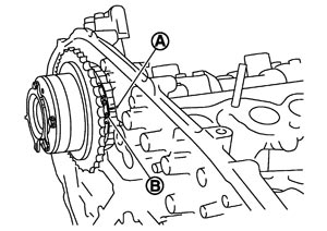
- It may be difficult to visually check the dislocation of matching marks (B) during and after installation. To make the matching easier, make a matching mark (A) on the top of sprocket teeth and its extended line in advance with paint.
- Secure camshaft using a wrench at the hexagonal portion to tighten mounting bolts.
1 : Camshaft (INT) : Engine front
■ CAUTION ■
Matching marks between timing chain and sprockets slip easily. Confirm all matching mark positions repeatedly during the installation process.-
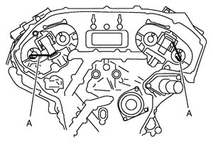
(1)Push plunger of timing chain tensioner (secondary) and keep it pressed in with a stopper pin (A).
-
(2)Install timing chains (secondary) and camshaft sprockets.
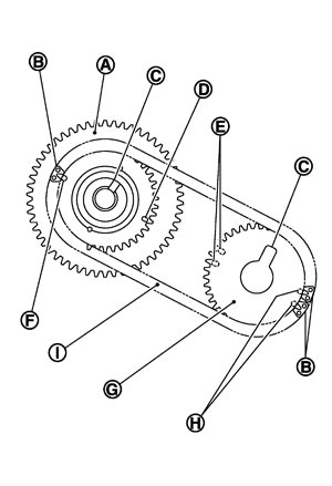
| A | : Camshaft sprocket (INT) back face |
| B | : Orange link |
| C | : Dowel groove |
| D | : Matching mark (oval) |
| E | : Matching mark (2 oval) |
| F | : Matching mark (circle) |
| G | : Camshaft sprocket (EXH) back face |
| H | : Matching mark (2 circle) |
| I | : Timing chain (secondary) |
-
(3)After confirming the matching marks are aligned, tighten camshaft sprocket mounting bolts.
-
(4)Pull stopper pins (C) out from timing chain tensioners (secondary) (1), (2).
| A | : Bank 1 |
| B | : Bank 2 |
- 6.Install the crankshaft sprocket and the oil pump related parts as follows:
- Check that the matching mark (C) on crankshaft sprocket face the front of the engine.
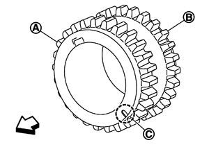
A : Timing chain (primary) side B : Oil pump drive chain side : Engine front - Check that the hexagonal portion of oil pump sprocket face the front of the engine.NOTE:There is no matching mark in the oil pump related parts.
- Insert the spring (B) into the fixing hole (A) on the front side of cylinder block before tighten mounting bolt.
- Check that the tension is applied to the oil pump drive chain after installing.
-
(1)Install oil pump. Refer to Exploded View (GT-R certified NISSAN dealer).
-
(2)Install the crankshaft sprocket, the oil pump drive chain, and the oil pump sprocket at the same time.
-
(3)Hold the hexagonal portion of oil pump sprocket, and then tighten the oil pump sprocket mounting nut.
| 1 | : Oil pump assembly |
-
(4)Install oil pump drive chain tensioner (1).
- 7.Install timing chain (primary) (1).
- Install timing chain (primary) so that the matching mark (punched) (B) on camshaft sprocket (INT) is aligned with the yellow link (A) on timing chain, while the matching mark (notched) (C) on crankshaft sprocket is aligned with the orange link (D) one on timing chain, as shown in the figure.
- When it is difficult to align matching marks of timing chain (primary) with each sprocket, gradually turn camshaft using wrench on the hexagonal portion to align it with the matching marks.
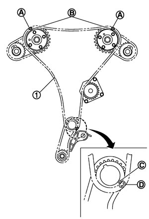
- 8.Install internal chain guide (1), slack guide (2) and tension guide (3).
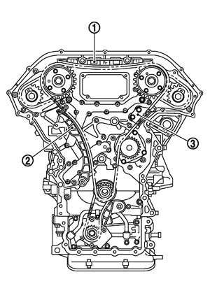
■ CAUTION ■
Never overtighten slack guide mounting bolts (2). It is normal for a gap (A) to exist under the bolt seats when mounting bolts are tightened to the specification.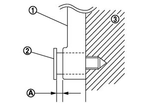
| 1 | : Slack guide |
| 3 | : Cylinder block |
- 9.Install the timing chain tensioner (primary) with the following procedure:
- The lever parts and the plunger stopper tab are synchronized. Therefore, the plunger will be secured under this condition.
- Remove any dirt and foreign materials completely from the back and the mounting surfaces of timing chain tensioner (primary).
-
(1)Pull plunger stopper tab (A) up (or turn lever downward) so as to remove plunger stopper tab from the ratchet of plunger (D).
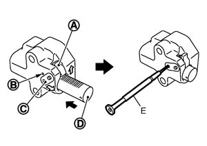
NOTE:
Plunger stopper tab and lever (C) are synchronized.-
(2)Push plunger into the inside of tensioner body.
-
(3)Hold plunger in the fully compressed position by engaging plunger stopper tab with the tip of ratchet.
-
(4)To secure lever, insert stopper pin (E) through hole of lever into tensioner body hole (B).
NOTE:
Figure shows the example of 1.2 mm (0.047 in) diameter thin screwdriver being used as the stopper pin.-
(5)Install timing chain tensioner (primary) (1).
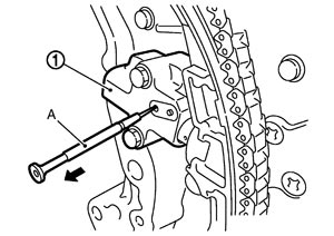
-
(6)Pull out stopper pin (A) after installing, and then release plunger.
- 10.Check again that the matching marks on sprockets and timing chain have not slipped out of alignment.
- 11.Install new O-rings (1) on rear timing chain case.
| A | : Bank 1 |
| B | : Bank 2 |
- 12.Install new front oil seal on front timing chain case as follows:
- Check the garter spring is in position and seal lip is not inverted.
-
(1)Apply neutral detergent on the rim.
-
(2)Install it so that each seal lip is oriented as shown in the figure.
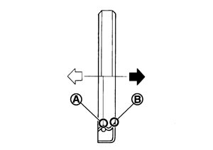
| B | : Dust seal lip |
| : Engine inside |
| : Engine outside |
■ CAUTION ■
Never touch oil seal lip (A).-
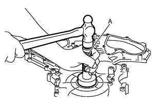
(3)Using a suitable drift (A), press-fit oil seal until it becomes flush with front timing chain case end face.
- 13.Install front timing chain case as follows:
- There are three types of mounting bolts. Refer to the following for locating bolts.
M10 bolts : 1, 2, 3, 4, 5, 6  : 80.0 N·m (8.2 kg-m, 59 ft-lb)
M8 bolts : 7, 8, 9, 10, 11, 12, 13, 14 : 35.0 N·m (3.6 kg-m, 26 ft-lb)M6 bolts : Except the above : 13.5 N·m (1.4 kg-m, 10 ft-lb)
-
(1)Apply a continuous bead of liquid gasket with the cartridge gun (commercial service tool) to front timing chain case back side as shown in the figure.
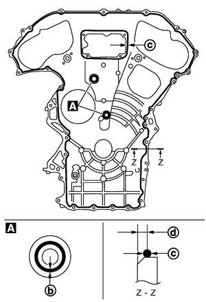
Use Genuine RTV Silicone Sealant or equivalent. Refer to Recommended Chemical Products and Sealants.
| b | : φ2.6 - 3.6 mm (0.102 - 0.142 in) dia. |
| c | : φ3.4 - 4.4 mm (0.134 - 0.173 in) dia. |
| d | : 4.0 - 5.6 mm (0.157 - 0.220 in) dia. |
-
(2)Tighten mounting bolts to the specified torque in numerical order as shown in the figure.
-
(3)After all bolts are tightened, retighten them to the specified torque in numerical order shown in the figure.
- 14.Install intake valve timing control covers as follows:
- Align the center of both shaft holes of the shaft and the intake side camshaft sprocket, and then insert them.
- Be careful not to drop the seal ring from the shaft groove.
- After all bolts are tightened, tighten No. 1 bolt to the specified torque again.
-
(1)Install new seal rings (1) in shaft grooves.
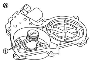
| A | : Bank 2 |
■ CAUTION ■
When replacing seal ring, replace all rings with new one.-
(2)Install intake valve timing control cover with new gasket to front timing chain case.
■ CAUTION ■
-
(3)Being careful not to move seal ring from the installation groove, align dowel pins on front timing chain case with dowel pin holes (C) to install intake valve timing control covers.
| A | : Bank 1 |
| B | : Bank 2 |
-
(4)Tighten mounting bolts in numerical order as shown in the figure.
- 15.Install crankshaft pulley as follows:
- When press-fitting crankshaft pulley with plastic hammer, tap on its center portion (not circumference).
- Place a matching mark (A) on crankshaft pulley (2) aligning with the matching (C) of crankshaft pulley bolt (1).
Angle tightening: 90 degrees (b)
-
(1)Fix crankshaft with a ring gear stopper [SST: KV101056S0 (J-49374)]. Refer to Setting (GT-R certified NISSAN dealer).
-
(2)Install crankshaft pulley, taking care not to damage front oil seal.
-
(3)Tighten crankshaft pulley bolt.
| : 44.1 N·m (4.5 kg-m, 33 ft-lb) |
-
(4)Tighten crankshaft pulley bolt (clockwise).
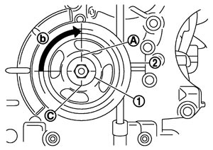
-
(5)Rotate crankshaft pulley in normal direction (clockwise when viewed from front) to confirm it turns smoothly.
- 16.Install drive belt auto-tensioner bracket (1) and power steering oil pump bracket (2) as follows:
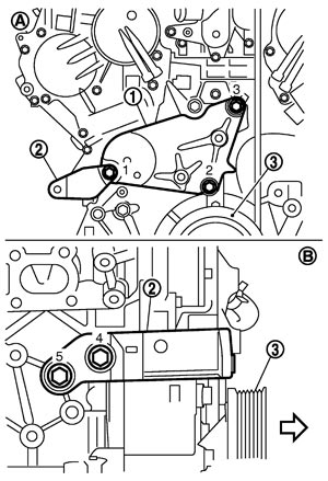
| 3 | : Crankshaft pulley |
| A | : Engine front side |
| B | : Engine right side |
| : Engine front |
-
(1)Tighten mounting bolts in numerical order as shown in the figure. (temporarily)
-
(2)Tighten mounting bolts to specified torque in numerical order as shown in the figure.
- 17.For the following operations, perform steps in the reverse order of removal.
Inspection
INSPECTION AFTER DISASSEMBLY Timing Chain
Check for cracks and any excessive wear at link plates and roller links of timing chain. Replace timing chain as necessary.
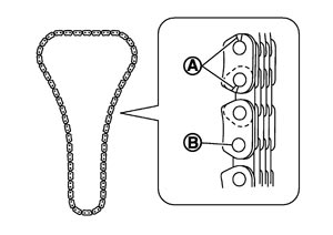
| A | : Crack |
| B | : Wear |
INSPECTION AFTER ASSEMBLY Inspection for LeaksThe following are procedures for checking fluids leak, lubricates leak.
- Before starting engine, check oil/fluid levels including engine coolant and engine oil. If less than required quantity, fill to the specified level. Refer to Fluids and Lubricants.
- Use procedure below to check for fuel leakage.
- Turn ignition switch “ON” (with engine stopped). With fuel pressure applied to fuel piping, check for fuel leakage at connection points.
- Start engine. With engine speed increased, check again for fuel leakage at connection points.
- Run engine to check for unusual noise and vibration.NOTE:If hydraulic pressure inside chain tensioner drops after removal/installation, slack in guide may generate a pounding noise during and just after the engine start. However, this does not indicate an unusualness. Noise will stop after hydraulic pressure rises.
- Warm up engine thoroughly to check there is no leakage of fuel, or any oil/fluids including engine oil and engine coolant.
- Bleed air from lines and hoses of applicable lines, such as in cooling system.
- After cooling down engine, again check oil/fluid levels including engine oil and engine coolant. Refill to the specified level, if necessary.
Summary of the inspection items:Items Before starting engine Engine running After engine stopped Engine coolant Level Leakage Level Engine oil Level Leakage Level Other oils and fluid* Level Leakage Level Fuel Leakage Leakage Leakage * Transmission/transaxle/CVT fluid, power steering fluid, brake fluid, etc.