CAMSHAFT
Exploded View
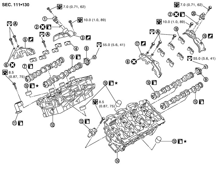
|
1. |
Camshaft position sensor (PHASE) (bank 1) |
2. |
O-ring |
3. |
Camshaft sensor bracket (bank 1) |
|
4. |
Camshaft bracket (No. 2 - 4) (bank 1) |
5. |
Camshaft bracket (No. 1) (bank 1) |
6. |
Seal washer |
|
7. |
Camshaft (EXH) (bank 1) |
8. |
Camshaft (INT) (bank 1) |
9. |
Camshaft signal plate |
|
10. |
Valve lifter |
11. |
Timing chain tensioner (secondary) (bank 1) |
12. |
Cylinder head (bank 1) |
|
13. |
Timing chain tensioner (secondary) (bank 2) |
14. |
Cylinder head (bank 2) |
15. |
Camshaft (EXH) (bank 2) |
|
16. |
Camshaft (INT) (bank 2) |
17. |
Camshaft bracket (No. 1) (bank 2) |
18. |
Camshaft bracket (No. 2 - 4) (bank 2) |
|
19. |
Camshaft sensor bracket (bank 2) |
20. |
Camshaft position sensor (PHASE) (bank 2) |
|
|
|
A. |
Refer to Disassembly and Assembly (GT-R certified NISSAN dealer) |
|
|
|
|
|
Refer to Components for symbols in the figure. |
|||||
Disassembly and Assembly
 DISASSEMBLY
- 1.Remove front timing chain case, rear timing chain case, camshaft sprocket and timing chain. Refer to Exploded View (GT-R certified NISSAN dealer).
- 2.Remove camshaft sensor bracket.
- Loosen mounting bolts in reverse order as shown in the figure.
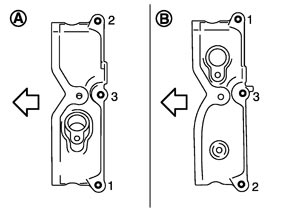
| A | : Bank 1 |
| B | : Bank 2 |
 | : Engine front |
- 3.Remove camshaft brackets.
- Mark camshafts, camshaft brackets and bolts so they are placed in the same position and direction for installation.
- Equally loosen camshaft bracket bolts in several steps in reverse order as shown in the figure.
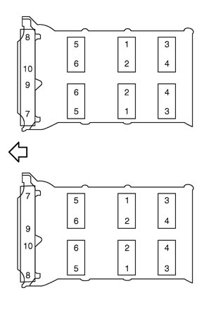
| : Engine front |
- 4.Remove timing chain tensioners (secondary) (1) from cylinder head.
- Remove timing chain tensioners (secondary) with its stopper pin (C) attached.
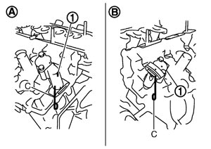
| A | : Bank 1 |
| B | : Bank 2 |
- 5.Remove camshaft.
- 6.Remove valve lifter.
- Identify installation positions, and store them without mixing them up.
- 7.Remove camshaft position sensor (PHASE), if necessary.
■ CAUTION ■
Never shock camshaft position sensors. ASSEMBLY- 1.Install valve lifter.
- Install it in the original position.
- 2.Install camshafts.
- Follow your identification marks made during removal, or follow the identification marks that are present on new camshafts for proper placement and direction.
Bank Camshaft Paint marks Identification mark (A) M1 (C) M2 (D) M3 (B) Bank 1 EXH (1) No White Light blue 1R INT (2) White No Light blue 1Q Bank 12 INT (3) White No Light blue 1S EXH (4) No White Light blue 1T - Install camshaft so that dowel pin (A) on front end face are positioned as shown in the figure. (No. 1 cylinder TDC on its compression stroke)
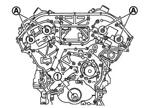
1 : Crankshaft key NOTE:Though camshaft does not stop at the portion as shown in the figure, for the placement of cam nose, it is generally accepted camshaft is placed for the same direction of the figure.
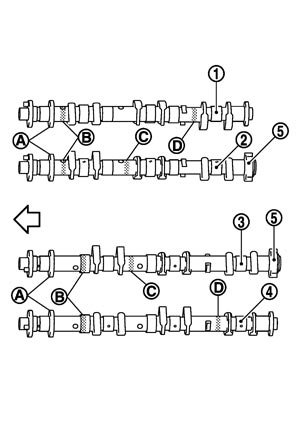
| 5 | : Camshaft signal plate |
| : Engine front |
- 3.Install timing chain tensioners (secondary) (1) on both sides of cylinder head.
- Install timing chain tensioner with its stopper pin (C) attached.
- Install timing chain tensioner with sliding part facing downward on cylinder head (bank 1), and with sliding part facing upward on cylinder head (bank 2).
| A | : Bank 1 |
| B | : Bank 2 |
- 4.Install camshaft brackets as follows.
- Install camshaft brackets (No. 2 to 4) aligning the stamp marks (A) as shown in the figure.
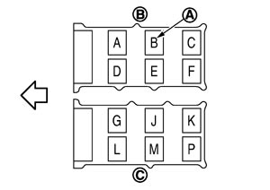
B : Bank 1 C : Bank 2 : Engine front NOTE:There are no identification marks indicating bank 1 and bank 2 for camshaft bracket (No. 1).
-
(1)Remove foreign material completely from camshaft bracket backside and from cylinder head installation face.
-
(2)Install camshaft bracket in original position and direction as shown in figure.
-
(3)Apply liquid gasket to mating surface of camshaft bracket (No. 1) as shown on both bank 1 and bank 2.
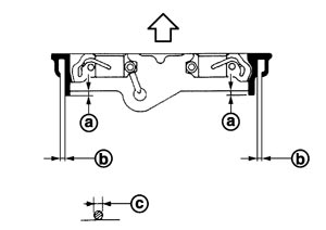
| a | : 2 mm (0.08 in) |
| b | : Clearance 5 mm (0.20 in) |
| c | : φ2.5 mm (0.098 in) |
| : Engine front |
Use Genuine RTV Silicone Sealant or equivalent. Refer to Recommended Chemical Products and Sealants.
- 5.Tighten camshaft bracket bolts in the following steps, in numerical order as shown.
| : Engine front |
-
(1)Tighten No. 7 to 10 in numerical order as shown.
 : 2.0 N·m (0.20 kg-m, 1 ft-lb) : 2.0 N·m (0.20 kg-m, 1 ft-lb) |
-
(2)Tighten No. 1 to 6 in numerical order as shown.
| : 2.0 N·m (0.20 kg-m, 1 ft-lb) |
-
(3)Tighten No. 1 to 10 in numerical order as shown.
| : 5.9 N·m (0.60 kg-m, 4 ft-lb) |
-
(4)Tighten No. 1 to 10 in numerical order as shown.
| : 10.4 N·m (1.1 kg-m, 8 ft-lb) |
- 6.Measure difference in levels between front end camshaft bracket (No. 1) and cylinder head.
- Measure two positions (both intake and exhaust side) for a single bank.
- If the measured value is out of the standard, re-install camshaft bracket (No. 1).
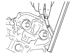
| Standard | : –0.14 to 0.14 mm (–0.0055 to 0.0055 in) |
- 7.Install camshaft sensor bracket as follows:
-
(1)Apply liquid gasket to mating surface of camshaft sensor bracket as shown in the figure.
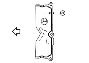
Use Genuine RTV Silicone Sealant or equivalent. Refer to Recommended Chemical Products and Sealants.
| a | : φ2.5 mm (0.098 in) |
| : Engine front |
-
(2)Tighten mounting bolts in numerical order as shown in the figure.
| A | : Bank 1 |
| B | : Bank 2 |
| : Engine front |
- 8.Inspect and adjust the valve clearance. Refer to Inspection (GT-R certified NISSAN dealer) and Inspection (GT-R certified NISSAN dealer).
- 9.Install in the reverse order of removal after this step.
Inspection
VALVE CLEARANCE ADJUSTMENT- Perform adjustment depending on selected head thickness of valve lifter.
- 1.Measure the valve clearance. Refer to Inspection (GT-R certified NISSAN dealer).
- 2.Remove camshaft. Refer to Disassembly and Assembly (GT-R certified NISSAN dealer).
- 3.Remove valve lifters at the locations that are out of the standard.
- 4.Measure the center thickness of the removed valve lifters with a micrometer (A).
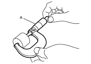
- 5.Use the equation below to calculate valve lifter thickness for replacement.
- Thickness of new valve lifter can be identified by stamp marks on the reverse side (inside the cylinder).
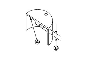
Stamp mark 788 indicates 7.88 mm (0.3102 in) in thickness.A : Stamp B : Thickness of valve lifter
| Valve lifter thickness calculation: | t = t1+ (C1 – C2) | ||||
| t | = Valve lifter thickness to be replaced | ||||
| t1 | = Removed valve lifter thickness | ||||
| C1 | = Measured valve clearance | ||||
| C2 | = Standard valve clearance: | ||||
| Intake | : 0.30 mm (0.012 in) | ||||
| Exhaust | : 0.33 mm (0.013 in) | ||||
Available thickness of valve lifter: 27 sizes with range 7.88 to 8.40 mm (0.3102 to 0.3307 in) in steps of 0.02 mm (0.0008 in) (when manufactured at factory). Refer to Camshaft (GT-R certified NISSAN dealer).
- 6.Install selected valve lifter.
- 7.Install camshaft. Refer to Disassembly and Assembly (GT-R certified NISSAN dealer).
- 8.Manually turn crankshaft pulley a few turns.
- 9.Check that the valve clearances for cold engine are within the specifications by referring to the specified values. Refer to Inspection (GT-R certified NISSAN dealer).
- 10.Install all removal parts in the reverse order of removal.
- 11.Warm up the engine, and check for unusual noise and vibration.
INSPECTION AFTER DISASSEMBLY Camshaft Runout
- 1.Put V-block on precise flat table, and support No. 2 and 4 journals of camshaft.
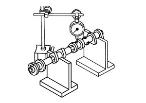
■ CAUTION ■
Never support No. 1 journal (on the side of camshaft sprocket) because it has a different diameter from the other three locations.- 2.Set a dial indicator vertically to No. 3 journal.
- 3.Turn camshaft to one direction with hands, and measure the camshaft runout on a dial indicator. (Total indicator reading)
| Standard & limit | : Refer to Camshaft (GT-R certified NISSAN dealer). |
- 4.If it exceeds the limit, replace camshaft.
Camshaft Cam Height- 1.Measure the camshaft cam height with a micrometer.
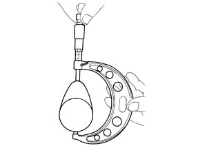
| Standard & limit | : Refer to Camshaft (GT-R certified NISSAN dealer). |
- 2.If wear exceeds the limit, replace camshaft.
Camshaft Journal Oil ClearanceCAMSHAFT JOURNAL DIAMETER
- Measure the outer diameter of camshaft journal with a micrometer (A).
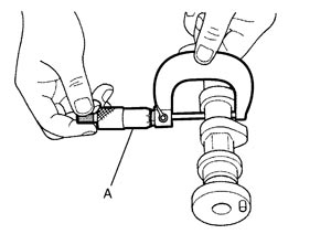
Standard : Refer to Camshaft (GT-R certified NISSAN dealer).
CAMSHAFT BRACKET INNER DIAMETER
- Tighten camshaft bracket bolt with the specified torque. Refer to “ASSEMBLY” for the tightening procedure.
- Measure inner diameter (A) of camshaft bracket with a bore gauge.
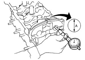
Standard : Refer to Camshaft (GT-R certified NISSAN dealer).
CAMSHAFT JOURNAL OIL CLEARANCE
- (Oil clearance) = (Camshaft bracket inner diameter) – (Camshaft journal diameter).
Limit : Refer to Camshaft (GT-R certified NISSAN dealer). - If the calculated value exceeds the limit, replace either or both camshaft and cylinder head.NOTE:Camshaft brackets cannot be replaced as single parts, because there are machined together with cylinder head. Replace whole cylinder head assembly.
Camshaft End Play- Install a dial indicator in thrust direction on front end of camshaft. Measure the end play of a dial indicator when camshaft is moved forward/backward (in direction to axis).
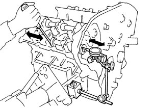
Standard and limit : Refer to Camshaft (GT-R certified NISSAN dealer). - Measure the following parts if out of the limit.
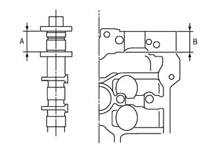
- Dimension “A” for camshaft No. 1 journal
Standard : 27.500 - 27.548 mm (1.0827 - 1.0846 in) - Dimension “B” for cylinder head No. 1 journal bearing
Standard : 27.360 - 27.385 mm (1.0772 - 1.0781 in) - Refer to the standards above, and then replace camshaft and/or cylinder head.
Camshaft Sprocket Runout- 1.Put V-block on precise flat table, and support No. 2 and 4 journals of camshaft.
■ CAUTION ■
Never support No. 1 journal (on the side of camshaft sprocket) because it has a different diameter from the other three locations.- 2.Measure the camshaft sprocket runout with a dial indicator. (Total indicator reading)
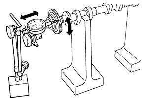
| Limit | : Refer to Camshaft (GT-R certified NISSAN dealer). |
- If it exceeds the limit, replace camshaft sprocket.
Camshaft Signal Plate Runout- 1.Put V-block on precise flat table, and support No. 2 and 4 journals of camshaft.
■ CAUTION ■
Never support No. 1 journal (on the side of camshaft sprocket) because it has a different diameter from the other three locations.- 2.Measure the camshaft signal plate runout with a dial indicator. (Total indicator reading)
| Limit | : Refer to Camshaft (GT-R certified NISSAN dealer). |
- If it exceeds the limit, replace camshaft signal plate.
Valve Lifter Check if surface of valve lifter has any wear or cracks.
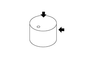
- If anything above is found, replace valve lifter. Refer to Camshaft (GT-R certified NISSAN dealer).
Valve Lifter ClearanceVALVE LIFTER OUTER DIAMETER
- Measure the outer diameter at 1/2 height of valve lifter with a micrometer (A) since valve lifter is in barrel shape.
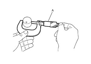
Standard : Refer to Camshaft (GT-R certified NISSAN dealer).
VALVE LIFTER HOLE DIAMETER
- Measure the inner diameter of valve lifter hole of cylinder head with an inside micrometer.
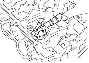
Standard : Refer to Camshaft (GT-R certified NISSAN dealer).
VALVE LIFTER CLEARANCE
- (Valve lifter clearance) = (Valve lifter hole diameter) – (Valve lifter outer diameter)
Standard : Refer to Camshaft (GT-R certified NISSAN dealer). - If the calculated value is out of the standard, referring to each standard of valve lifter outer diameter and valve lifter hole diameter, replace either or both valve lifter and cylinder head.
INSPECTION AFTER ASSEMBLY Inspection of Camshaft Sprocket (INT) Oil Groove■ CAUTION ■
- Perform this inspection only when DTC P0011, P0021 are detected in self‐diagnostic results of CONSULT‐III and it is directed according to inspection procedure of EC section. Refer to DTC Logic (GT-R certified NISSAN dealer).
- Check when engine is cold so as to prevent burns from the splashing engine oil.
- 1.Check engine oil level. Refer to Inspection.
- 2.Perform the following procedure so as to prevent the engine from being unintentionally started while checking.
-
(1)Release the fuel pressure. Refer to Inspection (GT-R certified NISSAN dealer).
-
(2)Disconnect ignition coil and injector harness connectors. Refer to Exploded View.
- 3.Remove intake valve timing control solenoid valve. Refer to Exploded View (GT-R certified NISSAN dealer).
- 4.Crank engine, and then check that engine oil comes out from intake valve timing control solenoid valve hole (A). End crank after checking.
- Prevent splashing by using a shop cloth so as to prevent the worker from injury from engine oil and so as to prevent engine oil contamination.
- Prevent splashing by using a shop cloth so as to prevent engine oil from being splashed to engine and vehicle. Especially, be careful no to apply engine oil to rubber parts of drive belts, engine mounting insulator, etc. Wipe engine oil off immediately if it is splashed.
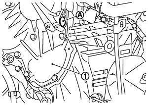
| 1 | : Intake valve timing control cover (bank 1) |
■ WARNING ■
Be careful not to touch rotating parts. (drive belts, idler pulley, and crankshaft pulley, etc.)■ CAUTION ■
- 5.Perform the following inspection if engine oil does not come out from intake valve timing control solenoid valve oil hole of the cylinder head.
- Remove oil filter, and then clean it. Refer to Exploded View (GT-R certified NISSAN dealer).
- Clean oil groove between oil strainer and intake valve timing control solenoid valve. Refer to Engine Lubrication System (GT-R certified NISSAN dealer).
- 6.Remove components between intake valve timing control solenoid valve and camshaft sprocket (INT), and then check each oil groove for clogging.
- Clean oil groove if necessary. Refer to Engine Lubrication System (GT-R certified NISSAN dealer).
- 7.After inspection, install removed parts in the reverse order.
Inspection for LeaksThe following are procedures for checking fluids leak, lubricates leak.
- Before starting engine, check oil/fluid levels including engine coolant and engine oil. If less than required quantity, fill to the specified level. Refer to Fluids and Lubricants.
- Use procedure below to check for fuel leakage.
- Turn ignition switch “ON” (with engine stopped). With fuel pressure applied to fuel piping, check for fuel leakage at connection points.
- Start engine. With engine speed increased, check again for fuel leakage at connection points.
- Run engine to check for unusual noise and vibration.NOTE:If hydraulic pressure inside timing chain tensioner drops after removal/installation, slack in the guide may generate a pounding noise during and just after engine start. However, this is normal. Noise will stop after hydraulic pressure rises.
- Warm up engine thoroughly to check there is no leakage of fuel, or any oil/fluids including engine oil and engine coolant.
- Bleed air from lines and hoses of applicable lines, such as in cooling system.
- After cooling down engine, again check oil/fluid levels including engine oil and engine coolant. Refill to the specified level, if necessary.
Summary of the inspection items:Items Before starting engine Engine running After engine stopped Engine coolant Level Leakage Level Engine oil Level Leakage Level Other oils and fluid* Level Leakage Level Fuel Leakage Leakage Leakage *: Transmission/transaxle/CVT fluid, power steering fluid, brake fluid, etc.