OIL PAN AND OIL STRAINER
Exploded View
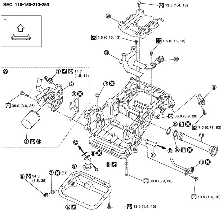
|
1. |
Oil pressure switch |
2. |
Oil filter bracket |
3. |
Gasket |
|
4. |
Oil filter |
5. |
Oil pan drain plug |
6. |
Oil pan (lower) |
|
7. |
Drain plug washer |
8. |
Oil strainer |
9. |
Gasket |
|
10. |
Oil pan (upper) |
11. |
Oil return hose |
12. |
Oil level sensor |
|
13. |
Axle pipe |
14. |
O-ring |
15. |
O-ring |
|
16. |
Crankshaft position sensor (POS) |
17. |
O-ring |
18 |
Baffle plate |
|
19. |
Baffle plate |
20. |
Baffle plate |
|
|
|
A. |
Refer to Exploded View (GT-R certified NISSAN dealer) |
B. |
Refer to Removal and Installation |
C. |
To oil pump |
|
D. |
To exhaust manifold and turbocharger assembly (bank 2) |
|
|
|
|

|
: Oil pan side |
|
|
|
|
|
Refer to Components for symbols in the figure. |
|||||
Disassembly and Assembly
 DISASSEMBLY
■ CAUTION ■
Never remove/install liquid gasket-applied oil pans (lower and upper) more than once. Replace them with new ones for a second or further removal/installation.
- 1.Remove oil pan (lower).
- Loosen mounting bolts in the reverse order as shown in the figure with power tool.
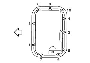
: Engine front - Insert the seal cutter [SST: KV10111100 (J37228)] between oil pan (upper) and oil pan (lower).
■ CAUTION ■
Never allow the mounting surface of oil pan (upper) to get scratched because it is surface-treated.NOTE:
The figure shows downward gaze.- 2.Remove oil strainer.
- 3.Remove front timing chain case, timing chain (primary) and oil pump drive chain. Refer to Exploded View (GT-R certified NISSAN dealer).
- 4.Remove oil pump. Refer to Exploded View (GT-R certified NISSAN dealer).
- 5.Remove oil pan (upper) as follows:
- Never allow the mounting surface of oil pan (upper) to get scratched because it is surface-treated.
- Never use the seal cutter.
-
(1)Loosen mounting bolts in the reverse order as shown in the figure with power tool.
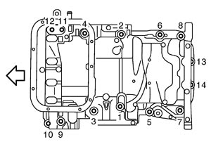
| : Engine front |
-
(2)Pry off the notch (B) located at the rear of oil pan (upper) (2) with a suitable tool (A) to separate the liquid gasket.
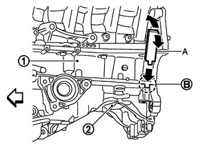
| 1 | : Lower cylinder block |
| : Engine front |
■ CAUTION ■
- 6.Remove O-rings (2).
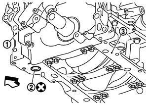
| 1 | : Rear timing chain case |
| 3 | : Lower cylinder block |
| : Engine front |
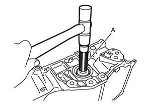
- 7.Remove axle pipe, if necessary.
- Remove axle pipe from oil pan (upper) using a suitable drift (A) [outer diameter: φ37 mm (1.46 in)].
 ASSEMBLY
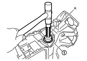
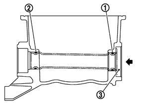
- 1.Install axle pipe (3) to oil pan (upper), if removed.
- Lubricate O-ring groove of axle pipe, O-rings, and O-ring joint of oil pan with new engine oil.
Unit: mm (in)
Items O-ring inner diameter Front final drive side (right side) O-ring (2) φ31.4 (1.236) Axle pipe flange side (left side) O-ring (1) φ33.6 (1.323) - Install axle pipe (1) to oil pan (upper) from axle pipe flange side (left side) using a suitable drift (A) [outer diameter: 43 to 57 mm (1.69 to 2.24 in)].
 ■ CAUTION ■Insert it with care to prevent O-ring from sliding.
- 2.Install oil pan (upper) as follows:
- For bolt holes with
 marks (3 locations), apply liquid gasket outside the holes.
 - Attaching should be done within 5 minutes after coating.
- There are four types of mounting bolts. Refer to the following for locating bolts.
M8 × 30 mm (1.18 in) : 5, 6, 13, 14 M8 × 40 mm (1.57 in) : 10 M8 × 60 mm (2.36 in) : 1, 2, 3, 4, 7, 8, 11, 12 M8 × 75 mm (2.95 in) : 9 - If not within the standard, repeat the installation procedure.
-
(1) Apply gasket remover (commercial service tool) on old liquid gasket adhered to the oil pan (upper).
-
(2)Remove gasket with a resin gasket scraper [SST: KV10119100 (J-49360) (A).
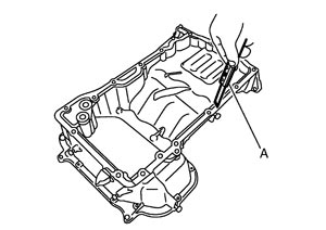
■ CAUTION ■
The mounting surface of oil pan (upper) is surface-treated. Be sure to use a resin gasket scraper so as not to damage the surface-treated.-
(3)Install new O-rings (2) on the bottom of lower cylinder block (3).
| 1 | : Rear timing chain case |
| : Engine front |
-
(4)Apply a continuous bead of liquid gasket with the cartridge gun (commercial service tool) to the oil pan (upper) as shown in the figure.
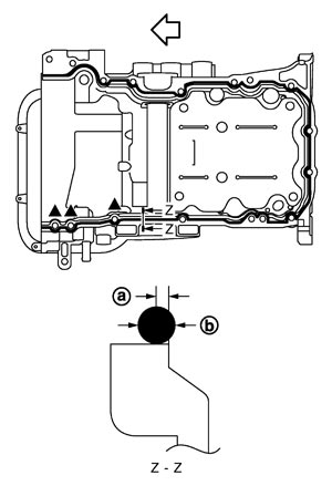
| a | : 1.5 mm (0.059 in) |
| b | : φ4.5 mm (0.177 in) |
| : Engine front |
Use Genuine RTV Silicone Sealant or equivalent. Refer to Recommended Chemical Products and Sealants.
■ CAUTION ■
-
(5)Tighten mounting bolts in numerical order as shown in the figure.
| : Engine front |
■ CAUTION ■
Install avoiding misalignment of O-rings.-
(6)After installing oil pan (upper) (2), check the front timing chain case mounting surface.
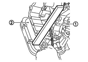
| 1 | : Rear timing chain case |
| Standard | : Less than 0.14 mm (0.006 in) |
- 3.Install oil pump. Refer to Exploded View (GT-R certified NISSAN dealer).
- 4.Install front timing chain case, timing chain (primary) and oil pump drive chain. Refer to Exploded View (GT-R certified NISSAN dealer).
- 5.Install oil strainer.
- 6.Install oil pan (lower) as follows:
-
(1)Apply a continuous bead of liquid gasket with the cartridge gun (commercial service tool) to the oil pan (lower) as shown in the figure.
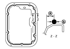
| a | : 8.5 mm (0.335 in) |
| b | : φ4.5 mm (0.177 in) |
Use Genuine RTV Silicone Sealant or equivalent. Refer to Recommended Chemical Products and Sealants.
■ CAUTION ■
Attaching should be done within 5 minutes after coating.-
(2)Tighten mounting bolts in numerical order as shown in the figure.
| : Engine front |
NOTE:
The figure shows downward gaze.- 7.Install oil pan drain plug.
- Refer to the figure of components of former page for installation direction of drain plug washer. Refer to Exploded View (GT-R certified NISSAN dealer).
- 8.Install in the reverse order of removal after this step.
NOTE:
At least 30 minutes after oil pan is installed, pour engine oil.Inspection
INSPECTION AFTER DISASSEMBLYClean oil strainer if any object attached.
INSPECTION AFTER ASSEMBLY- 1.Check the engine oil level and adjust engine oil. Refer to Inspection.
- 2.Start engine, and check there is no leak of engine oil.
- 3.Stop engine and wait for 10 minutes.
- 4.Check the engine oil level again. Refer to Inspection.