CYLINDER BLOCK
Exploded View
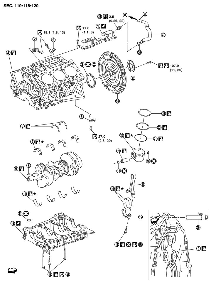
|
1. |
Breather separator |
2. |
Knock sensor |
3. |
Rear oil seal |
|
4. |
Cylinder block |
5. |
Thrust bearing |
6. |
Oil jet |
|
7. |
Main bearing (upper) |
8. |
Crankshaft key |
9. |
Crankshaft |
|
10. |
Main bearing (lower) |
11. |
O‐ring |
12. |
Lower cylinder block |
|
13. |
Lower cylinder block bolt |
14. |
Connecting rod bolt |
15. |
Connecting rod bearing cap |
|
16. |
Connecting rod bearing |
17. |
Connecting rod |
18. |
Snap ring |
|
19. |
Piston pin |
20. |
Piston |
21. |
Oil ring |
|
22. |
Second ring |
23. |
Top ring |
24. |
Flywheel |
|
25. |
Reinforcement plate |
26. |
Clamp |
27. |
PCV hose |
|
28. |
PCV valve |
29. |
Cylinder block heater (for Canada) |
|
|
|
A. |
To intake manifold collector |
B. |
Refer to Disassembly and Assembly (GT-R certified NISSAN dealer) |
C. |
Apply neutral detergent on the outer edge. |

|
: Engine front |
|
|
|
|
|
Refer to Components for symbols in the figure. |
|||||
Disassembly and Assembly
 DISASSEMBLY
- 1.Remove the following parts:
- Oil pans (lower and upper): Refer to Exploded View (GT-R certified NISSAN dealer).
- Front and rear timing chain case: Refer to Exploded View (GT-R certified NISSAN dealer).
- Cylinder head: Refer to Exploded View (GT-R certified NISSAN dealer).
- 2.Remove knock sensor.
■ CAUTION ■
Carefully handle knock sensor avoiding shocks.- 3.Remove breather separator.
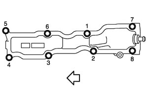
-
(1)Loosen mounting bolts in reverse order as shown in the figure.
| : Engine front |
- 4.Remove piston and connecting rod assembly with the following procedure:
- Before removing piston and connecting rod assembly, check the connecting rod side clearance. Refer to Inspection (GT-R certified NISSAN dealer).
■ CAUTION ■
Be careful not to drop connecting rod bearing, and to scratch the surface.-
(1)Position crankshaft pin corresponding to connecting rod to be removed onto the bottom dead center.
-
(2)Remove connecting rod bearing cap.
-
(3)Using a hammer handle or similar tool, push piston and connecting rod assembly out to the cylinder head side.
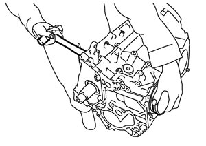
■ CAUTION ■
Be careful not to damage the cylinder wall and crankshaft pin, resulting from an interference of the connecting rod big end.- 5.Remove connecting rod bearings from connecting rod and connecting rod bearing cap.
- Be careful not to drop connecting rod bearing, and to scratch the surface.
- Identify installation positions, and store them without mixing them up.
■ CAUTION ■
- 6.Remove piston rings from piston.
- Before removing piston rings, check the piston ring side clearance. Refer to Inspection (GT-R certified NISSAN dealer).
- Use a piston ring expander (commercial service tool) (A).
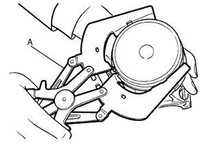
- When removing piston rings, be careful not to damage piston.
- Be careful not to damage piston rings by expanding them excessively.
■ CAUTION ■
- 7.Remove piston from connecting rod as follows:
-
(1)Using a snap ring pliers (A), remove snap rings.
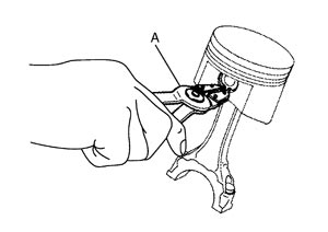
-
(2)Heat piston to 60 to 70°C (140 to 158°F) with an industrial use drier (A) or equivalent.
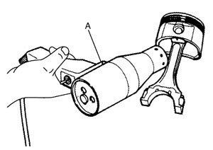
-
(3)Push out piston pin with stick of outer diameter approximately 20 mm (0.79 in).
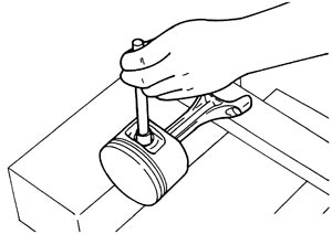
- 8.Remove lower cylinder block bolts as follows:
- Before loosening lower cylinder block bolts, measure the crankshaft end play. Refer to Inspection (GT-R certified NISSAN dealer).
-
(1)Loosen lower cylinder block bolts in several steps in the reverse order shown in the figure.
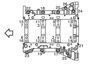
| : Engine front |
-
(2)Pry off the notch (A) located at lower cylinder block with a suitable tool to separate the liquid gasket.
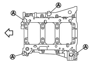
| : Engine front |
■ CAUTION ■
Be careful not to damage the mounting surfaces.- 9.Remove rear oil seal.
- 10.Remove crankshaft.
- 11.Remove main bearings and thrust bearings from cylinder block and lower cylinder block.
- Be careful not to drop main bearing, and to scratch the surface.
- Identify installation positions, and store them without mixing them up.
■ CAUTION ■
- 12.Remove oil jet.
ASSEMBLY- 1.Fully air-blow engine coolant and engine oil passages in cylinder block, cylinder bore and crankcase to remove any foreign material.
■ CAUTION ■
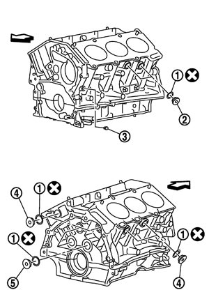
Use a goggles to protect your eye.- 2.Install each plug to cylinder block as shown in the figure.
- Apply sealant to the thread of water drain plug (3).Use Genuine RTV Silicone Sealant or equivalent. Refer to Recommended Chemical Products and Sealants.
- Apply sealant to the thread of plugs (2), (4).Use Genuine High Strength Thread Locking Sealant or equivalent. Refer to Recommended Chemical Products and Sealants.
- Replace washers (1) with new one.
- Tighten each plug as specified below.
Part Washer Tightening torque 2 Yes 53.9 N·m (5.5 kg-m, 40 ft-lb) 3 No New 6.0 N·m (0.61 kg-m, 4 ft-lb) Reused 9.8 N·m (1.0 kg-m, 7 ft-lb) 4 Yes 62.7 N·m (6.4 kg-m, 46 ft-lb) 5 Yes 78.0 N·m (8.0 kg-m, 58 ft-lb)
| : Engine front |
- 3.Install breather separator.
-
(1)Apply a continuous bead of liquid gasket with the cartridge gun (commercial service tool) to breather separator as shown in the figure.
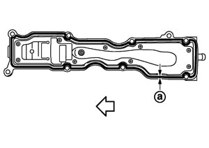
| a | : φ2.5 mm (0.098 in) dia |
| : Engine front |
Use Genuine RTV Silicone Sealant or equivalent. Refer toRecommended Chemical Products and Sealants.
-
(2)Tighten mounting bolts in reverse order as shown in the figure.
| : Engine front |
- 4.Install oil jet.
- Insert oil jet into cylinder block dowel pin hole (A), and tighten mounting bolts.
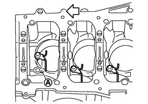
: Engine front
- 5.Install main bearings and thrust bearings as follows:
- Install thrust bearings (1) with the oil groove (E) facing crankshaft arm (outside).
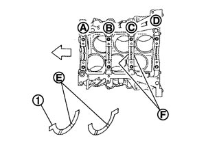
A : No. 1 B : No. 2 C : No. 3 D : No. 4 F : Thrust bearing installation position : Engine front - Main bearing with oil hole (B) and groove (C) goes on cylinder block. The one without them goes on lower cylinder block.
- Before installing main bearings, apply engine oil to the bearing surface (inside). Do not apply engine oil to the back surface, but thoroughly clean it.
- When installing, align main bearing stopper protrusion to cutout of cylinder block and lower cylinder block.
- Ensure the oil holes on cylinder block and those on the corresponding bearing are aligned.
■ CAUTION ■
Be careful not to drop main bearing, and to scratch the surface.-
(1)Remove dust, dirt, and engine oil on bearing mating surfaces of cylinder block and lower cylinder block.
-
(2)Install thrust bearings to the both sides of the No. 3 journal housing on cylinder block.
-
(3)Install main bearings paying attention to the direction.
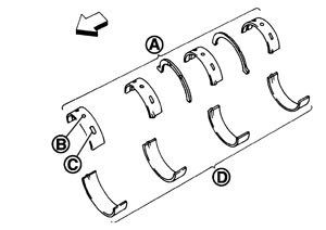
| A | : Cylinder block side |
| D | : Lower cylinder block side |
| : Engine front |
- 6.Install crankshaft to cylinder block.
- While turning crankshaft by hand, check that it turns smoothly.
- 7.Install lower cylinder block.
- Apply a continuous bead of liquid gasket with the cartridge gun (commercial service tool) to lower cylinder block as shown in the figure.
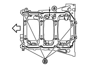
a : φ4.0 - 5.0 mm (0.157 ‐ 0.197 in) dia B : Apply to end : Engine front
Use Genuine RTV Silicone Sealant or equivalent. Refer toRecommended Chemical Products and Sealants.
NOTE:
Lower cylinder block cannot be replaced as a single part, because it is machined together with cylinder block.- 8.Inspect the outer diameter of lower cylinder block bolt. Refer to Inspection (GT-R certified NISSAN dealer).
- 9.Install lower cylinder block bolts in numerical order as shown in the figure as follows:
- After installing lower cylinder block bolts, check that crankshaft can be rotated smoothly by hand.
- Check the crankshaft end play. Refer to Inspection (GT-R certified NISSAN dealer).
-
(1)Apply new engine oil to threads and seat surfaces of lower cylinder block bolts.
-
(2)Tighten lower cylinder block bolts (No. 17 to 24) in numerical order as shown in the figure.
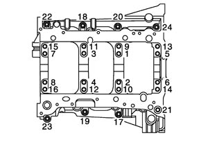
 : 25.0 N·m (2.6 kg-m, 18 ft-lb) : 25.0 N·m (2.6 kg-m, 18 ft-lb) |
-
(3)Repeat step b.
-
(4)Tighten lower cylinder block bolt (No. 1 to 16) in numerical order as shown in the figure.
| : 44.2 N·m (4.5 kg-m, 33 ft-lb) |
-
(5)Tighten lower cylinder block bolt (No. 1 to 16) (clockwise).
| Angle tightening : 90 degrees |
■ CAUTION ■
Use the angle wrench [SST: KV10112100 (BT8653-A)] (A) to check tightening angle. Never make judgment by visual inspection.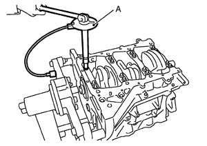
- 10.Install piston to connecting rod as follows:
- Insert it fully into groove to install.
- Using an industrial use drier or similar tool, heat piston until piston pin can be pushed in by hand without excess force [approx. 60 to 70°C (140 to 158°F)]. From the front to the rear, insert piston pin into piston and connecting rod.
- Assemble so that the front mark on the piston head and the cylinder number on connecting rod are positioned as shown in the figure.
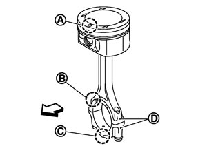
A : Front mark B : Oil groove C : Front mark D : Cylinder number : Engine front - Insert it fully into groove to install.
- After installing, check that connecting rod moves smoothly.
-
(1)Using a snap ring pliers, install new snap ring to the groove of piston rear side.
-
(2)Install piston to connecting rod.
-
(3)Install new snap ring to the groove of the piston front side.
- 11.Using a piston ring expander (commercial service tool) (A), install piston rings.
- When installing piston rings, be careful not to damage piston.
- Be careful not to damage piston rings by expending them excessively.
- If there is stamped mark on ring, mount it with marked side up.
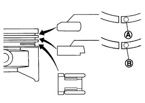
Stamped mark: Top ring (A) : R Second ring (B) : R2 - Position each ring with the gap as shown in the figure referring to the piston front mark (D).
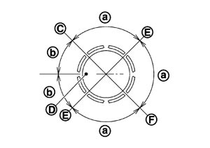
C : Top ring gap E : Oil ring upper or lower rail gap (either of them) F : Second ring and oil ring spacer gap a : 90 degrees b : 45 degrees - Check the piston ring side clearance. Refer to Inspection (GT-R certified NISSAN dealer).
■ CAUTION ■
- 12.Install connecting rod bearings to connecting rod and connecting rod bearing cap.
- Before installing connecting rod bearings, apply engine oil to the bearing surface (inside). Do not apply engine oil to the back surface, but thoroughly clean it.
- When installing, align connecting rod bearing stopper protrusion (B) with cutout (A) of connecting rods and connecting rod bearing caps to install.
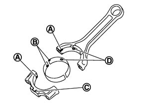
C : Front mark - Ensure the oil hole (D) on connecting rod and that on the corresponding bearing are aligned.
■ CAUTION ■
Be careful not to drop connecting rod bearing, and to scratch the surface.- 13.Install piston and connecting rod assembly to crankshaft.
- Position crankshaft pin corresponding to connecting rod to be installed onto the bottom dead center.
- Apply engine oil sufficiently to the cylinder bore, piston and crankshaft pin journal.
- Match the cylinder position with the cylinder number on connecting rod to install.
- Be sure that front mark on piston crown is facing front of engine.
- Using a piston ring compressor [SST: EM03470000 (J8037)] (A) or suitable tool, install piston with the front mark on the piston crown facing the front of the engine.
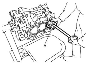
■ CAUTION ■
Be careful not to damage the cylinder wall and crankshaft pin, resulting from an interference of the connecting rod big end.- 14.Install connecting rod bearing cap.
- Match the stamped cylinder number marks on connecting rod with those on connecting rod bearing cap to install.
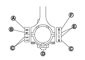
A : Small-end diameter grade B : Weight grade C : Management code E : Cylinder No. F : Big‐end diameter grade - Be sure that front mark (D) on connecting rod bearing cap is facing front of the engine.
- 15.Tighten connecting rod bolt as follows:
- After tightening connecting rod bolts, check that crankshaft rotates smoothly.
- Check the connecting rod side clearance. Refer to Inspection (GT-R certified NISSAN dealer).
■ CAUTION ■
Connecting rod bolts are nonreusable.-
(1)Apply engine oil to the threads and seats of connecting rod bolts.
-
(2)Tighten connecting rod bolts.
| : 28.4 N·m (2.9 kg-m, 21 ft-lb) |
-
(3)Completely loosen connecting rod bolts.
| : 0 N·m (0 kg-m, 0 ft-lb) |
-
(4)Tighten connecting rod bolts.
| : 24.5 N·m (2.5 kg-m, 18 ft-lb) |
-
(5)Tighten connecting rod bolts (clockwise).
| Angle tightening : 120 degrees |
■ CAUTION ■
Always use the angle wrench [SST: KV10112100 (BT8653-A)] (A). Avoid tightening based on visual check alone.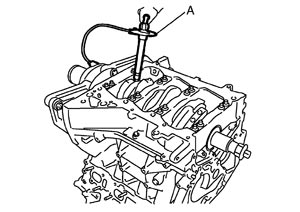
- 16.Install oil pan (upper). Refer to Exploded View (GT-R certified NISSAN dealer).
- 17.Install new rear oil seal as follows:
-
(1)Apply neutral detergent on the rim.
-
(2)Install it so that each seal lip is oriented as shown in the figure.
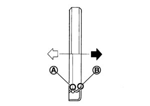
| B | : Dust seal lip |
| : Engine inside |
 | : Engine outside |
■ CAUTION ■
Never touch oil seal lip (A).-
(3)Press in rear oil seal (1) to the position as shown in the figure.
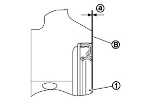
| a | : 0 - 0.5 mm (0 - 0.020 in) |
| B | : Cylinder block rear end face |
- 18.Install flywheel as follows:
- Ensure the dowel pin is installed in the crankshaft.■ CAUTION ■
- If these are not aligned correctly, engine runs roughly and “MIL” turns on.
- When handling signal plate, take care not to damage or scratch it.
- Never place drive plate with signal plate facing down.
- Handle signal plate in a manner that prevents it from becoming magnetized.
- If these are not aligned correctly, engine runs roughly and “MIL” turns on.
- Holding ring gear with the ring gear stopper [SST: KV101056S0 (J-49374)] (A).
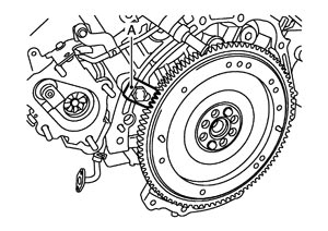
-
(1)Apply engine oil to the threads and seats of bolts.
-
(2)When installing flywheel (2) and to crankshaft (1), be sure to correctly align crankshaft side dowel pin (A) and flywheel side dowel pin hole.
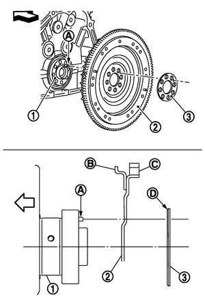
| 3 | : Reinforcement plate |
| B | : Signal plate |
| C | : Ring gear |
| D | : Rounded |
| : Engine front |
-
(3)Tighten flywheel mounting bolts crosswise over several times.
-
(4)Rotate crankshaft pulley in normal direction (clockwise when viewed from front) to confirm flywheel turns smoothly.
- 19.Install knock sensors.
- Install by aligning the matching mark (A) on the cylinder block.
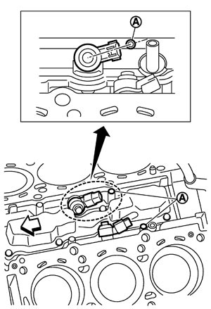
: Engine front - After installing knock sensor, connect harness connector, and lay it out to rear of the engine.
- Never tighten mounting bolts while holding connector.
- If any impact by dropping is applied to knock sensor, replace it with new one.
- Check that there is no foreign material on the cylinder block mating surface and the back surface of knock sensor.
- Check that knock sensor does not interfere with other parts.
■ CAUTION ■
NOTE:
- 20.Install in the reverse order of removal after this step.
Inspection
CRANKSHAFT END PLAY- Measure the clearance between thrust bearings and crankshaft arm when crankshaft is moved fully forward or backward with a dial indicator.
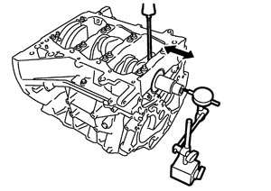
Standard and limit : Refer to Cylinder Block (GT-R certified NISSAN dealer). - If the measured value exceeds the limit, replace thrust bearings, and measure again. If it still exceeds the limit, replace crankshaft also.
CONNECTING ROD SIDE CLEARANCE- Measure the side clearance between connecting rod and crankshaft arm with a feeler gauge.
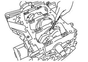
Standard and limit : Refer to Cylinder Block (GT-R certified NISSAN dealer). - If the measured value exceeds the limit, replace connecting rod, and measure again. If it still exceeds the limit, replace crankshaft also.
PISTON TO PISTON PIN OIL CLEARANCE Piston Pin Hole Diameter
Measure the inner diameter of piston pin hole with an inside micrometer (A).
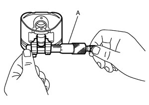
| Standard | : Refer to Cylinder Block (GT-R certified NISSAN dealer). |
Piston Pin Outer DiameterMeasure the outer diameter of piston pin with a micrometer (A).
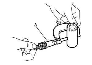
| Standard | : Refer to Cylinder Block (GT-R certified NISSAN dealer). |
Piston to Piston Pin Oil Clearance(Piston to piston pin oil clearance) = (Piston pin hole diameter) – (Piston pin outer diameter)
| Standard | : Refer to Cylinder Block (GT-R certified NISSAN dealer). |
- If the calculated value is out of the standard, replace piston and piston pin assembly.
- When replacing piston and piston pin assembly, refer to Description (GT-R certified NISSAN dealer).NOTE:
- Piston is available together with piston pin as assembly.
- Piston pin (piston pin hole) grade is provided only for the parts installed at the plant. For service parts, no piston pin grades can be selected. (Only “0” grade is available.)
- Piston is available together with piston pin as assembly.
PISTON RING SIDE CLEARANCE- Measure the side clearance of piston ring (1) and piston ring groove with a feeler gauge (C).
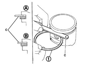
A : OK B : NG Standard and limit : Refer to Cylinder Block (GT-R certified NISSAN dealer). - If the measured value exceeds the limit, replace piston ring, and measure again. If it still exceeds the limit, replace piston also.
PISTON RING END GAP- Check that the cylinder bore inner diameter is within the specification.
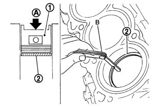
- Lubricate with new engine oil to piston (1) and piston ring (2), and then insert piston ring until middle of cylinder with piston, and measure the piston ring end gap with a feeler gauge (B).
A : Press-fit Standard and limit : Refer to Cylinder Block (GT-R certified NISSAN dealer). - If the measured value exceeds the limit, replace piston ring, and measure again. If it still exceeds the limit, replace cylinder block.
CONNECTING ROD BEND AND TORSION- Check with a connecting rod aligner.
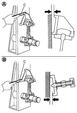
A : Bend B : Torsion C : Feeler gauge Bend limit : Refer to Cylinder Block (GT-R certified NISSAN dealer). Torsion limit - If it exceeds the limit, replace connecting rod assembly.
CONNECTING ROD BIG END DIAMETER- Install connecting rod bearing cap without installing connecting rod bearing, and tightening connecting rod bolts to the specified torque. Refer to Disassembly and Assembly (GT-R certified NISSAN dealer) for the tightening procedure.
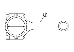
1 : Connecting rod - Measure the inner diameter of connecting rod big end with an inside micrometer.
Standard : Refer to Cylinder Block (GT-R certified NISSAN dealer). - If out of the standard, replace connecting rod assembly.
CONNECTING ROD BUSHING OIL CLEARANCE Connecting Rod Bushing Inner DiameterMeasure the inner diameter of connecting rod bushing with an inside micrometer (A).
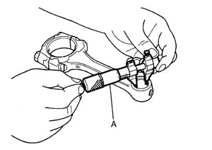
| Standard | : Refer to Cylinder Block (GT-R certified NISSAN dealer). |
Piston Pin Outer DiameterMeasure the outer diameter of piston pin with a micrometer (A).
| Standard | : Refer to Cylinder Block (GT-R certified NISSAN dealer). |
Connecting Rod Bushing Oil Clearance(Connecting rod bushing oil clearance) = (Connecting rod bushing inner diameter) – (Piston pin outer diameter)
| Standard and limit | : Refer to Cylinder Block (GT-R certified NISSAN dealer). |
- If the calculated value exceeds the limit, replace connecting rod assembly and/or piston and piston pin assembly.
- If replacing piston and piston pin assembly, refer to Description (GT-R certified NISSAN dealer).
- If replacing connecting rod assembly, refer to Connecting Rod Bearing (GT-R certified NISSAN dealer) to select the connecting rod bearing.
Factory installed parts grading:
- Service parts apply only to grade “0”.
Grade 0 1 Connecting rod bushing inner diameter * Refer to Cylinder Block (GT-R certified NISSAN dealer). Piston pin hole diameter Piston pin outer diameter *: After installing in connecting rod
CYLINDER BLOCK DISTORTION- Using a scraper, remove gasket on the cylinder block surface, and also remove engine oil, scale, carbon, or other contamination. ■ CAUTION ■Be careful not to allow gasket flakes to enter engine oil or engine coolant passages.
- Measure the distortion on the cylinder block upper face at some different points in six directions (C, D, E, F, G and H) with a straightedge (A) and a feeler gauge (B).
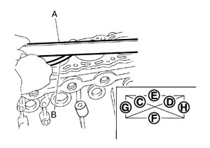
Limit : Refer to Cylinder Block (GT-R certified NISSAN dealer). - If it exceeds the limit, replace cylinder block.
MAIN BEARING HOUSING INNER DIAMETER- Install lower cylinder block (2) without installing main bearings, and tighten lower cylinder block bolts to the specified torque. Refer to Disassembly and Assembly (GT-R certified NISSAN dealer) for the tightening procedure.
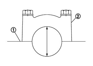
- Measure the inner diameter of main bearing housing with a bore gauge.
Standard : Refer to Cylinder Block (GT-R certified NISSAN dealer). - If out of the standard, replace cylinder block (1) and lower cylinder block as assembly.NOTE:Cylinder block cannot be replaced as a single part, because it is machined together with lower cylinder block.
PISTON TO CYLINDER BORE CLEARANCE Cylinder Bore Inner Diameter - Using a bore gauge, measure cylinder bore for wear, out-of-round and taper at six different points on each cylinder. [(A) and (B) directions at (C), (D) and (E)] is in longitudinal direction of engine.
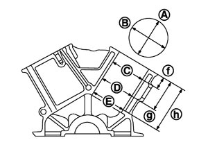
f : 10 mm (0.39 in) g : 60 mm (2.36 in) h : 135 mm (5.31 in) Standard and limit : Refer to Cylinder Block (GT-R certified NISSAN dealer). Wear limit Out-of-round (Difference between "A" and "B") Taper (Difference between "C" and "E") - If the measured value exceeds the limit, or if there are scratches and/or seizure on the cylinder inner wall, replace cylinder block. ■ CAUTION ■Cylinder bore is covered with coating. Never perform honing and boring.NOTE:Oversize pistons are not service parts.
Piston Skirt DiameterMeasure the outer diameter of piston skirt with a micrometer (A).
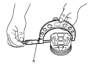
| Measure point | : Refer to Cylinder Block (GT-R certified NISSAN dealer). |
| Standard |
Piston‐to‐Cylinder Bore ClearanceCalculate by piston skirt diameter and cylinder bore inner diameter [direction (B), position (D)].
| A | : Longitudinal direction |
| C | : Top position |
| E | : Bottom position |
| f | : 10 mm (0.39 in) |
| g | : 60 mm (2.36 in) |
| h | : 135 mm (5.31 in) |
(Clearance) = (Cylinder bore inner diameter) – (Piston skirt diameter).
| Standard and limit | : Refer to Cylinder Block (GT-R certified NISSAN dealer). |
- If the calculated value exceeds the limit, replace either or both piston assembly and cylinder block. Refer to Disassembly and Assembly (GT-R certified NISSAN dealer).
CRANKSHAFT MAIN JOURNAL DIAMETER- Measure the outer diameter of crankshaft main journals with a micrometer.
Standard : Refer to Cylinder Block (GT-R certified NISSAN dealer). - If out of the standard, measure the main bearing oil clearance. Then use undersize bearing. Refer to Main Bearing (GT-R certified NISSAN dealer).
CRANKSHAFT PIN JOURNAL DIAMETER- Measure the outer diameter of crankshaft pin journal with a micrometer (A).
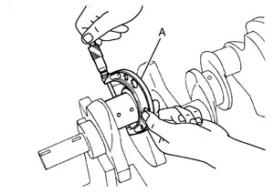
Standard : Refer to Cylinder Block (GT-R certified NISSAN dealer). - If out of the standard, measure the connecting rod bearing oil clearance. Then use undersize bearing. Refer to Connecting Rod Bearing (GT-R certified NISSAN dealer).
CRANKSHAFT OUT-OF-ROUND AND TAPER- Measure the dimensions at four different points as shown in the figure on each main journal and pin journal with a micrometer.
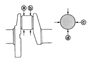
- Out-of-round is indicated by the difference in the dimensions between (d) and (c) at (a) and (b).
- Taper is indicated by the difference in the dimensions between.
Limit : Refer to Cylinder Block (GT-R certified NISSAN dealer). Out-of-round (Difference between "c" and "d") Taper (Difference between "a" and "b") - If the measured value exceeds the limit, correct or replace crankshaft.
- If corrected, measure the bearing oil clearance of the corrected main journal and/or pin journal. Then select the main bearing and/or connecting rod bearing. Refer to Main Bearing (GT-R certified NISSAN dealer) and/or Connecting Rod Bearing (GT-R certified NISSAN dealer).
CRANKSHAFT RUNOUT - Place V-block on precise flat table, and support the journals on the both end of crankshaft.
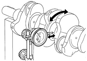
- Place a dial indicator straight up on the No. 3 journal.
- While rotating crankshaft, read the movement of the pointer on a dial indicator. (Total indicator reading)
Standard and limit : Refer to Cylinder Block (GT-R certified NISSAN dealer). - If it exceeds the limit, replace crankshaft.
CONNECTING ROD BEARING OIL CLEARANCE Method by Calculation- Install connecting rod bearings (1) to connecting rod (2) and connecting rod cap, and tighten connecting rod bolts to the specified torque. Refer to Disassembly and Assembly (GT-R certified NISSAN dealer) for the tightening procedure.
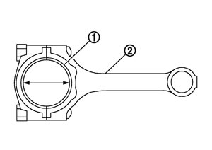
- Measure the inner diameter of connecting rod bearing with an inside micrometer.
| Standard and limit | : Refer to Connecting Rod Bearing (GT-R certified NISSAN dealer). | |
- If the calculated value exceeds the limit, select proper connecting rod bearing according to connecting rod big end diameter and crankshaft pin journal diameter to obtain the specified bearing oil clearance. Refer to Connecting Rod Bearing (GT-R certified NISSAN dealer).
Method of Using Plastigage- Remove oil and dust on crankshaft pin journal and the surfaces of each bearing completely.
- Cut a plastigage slightly shorter than the bearing width, and place it in crankshaft axial direction, avoiding oil holes.
- Install connecting rod bearings to connecting rod and connecting rod bearing cap, and tighten connecting rod bolts to the specified torque. Refer to Disassembly and Assembly (GT-R certified NISSAN dealer) for the tightening procedure.■ CAUTION ■Never rotate crankshaft.
- Remove connecting rod bearing cap and bearings, and using the scale on the plastigage bag, measure the plastigage width.
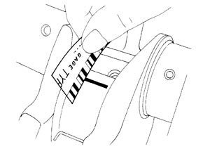 NOTE:The procedure when the measured value exceeds the limit is same as that described in the “Method by Calculation”.
MAIN BEARING OIL CLEARANCE Method by Calculation- Install main bearings (3) to cylinder block (1) and lower cylinder block (2), and tighten lower cylinder block bolts to the specified torque. Refer to Disassembly and Assembly (GT-R certified NISSAN dealer) for the tightening procedure.
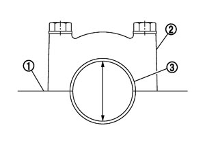
- Measure the inner diameter of main bearing with a bore gauge.
| Standard and limit | : Refer to Main Bearing (GT-R certified NISSAN dealer). | |
- If the calculated value exceeds the limit, select proper main bearing according to main bearing inner diameter and crankshaft main journal diameter to obtain the specified bearing oil clearance. Refer to Main Bearing (GT-R certified NISSAN dealer).
Method of Using Plastigage- Remove engine oil and dust on crankshaft journal and the surfaces of each bearing completely.
- Cut a plastigage slightly shorter than the bearing width, and place it in crankshaft axial direction, avoiding oil holes.
- Install main bearing to cylinder block and lower cylinder block, and tighten lower cylinder block bolts with lower cylinder block to the specified torque. Refer to Disassembly and Assembly (GT-R certified NISSAN dealer) for the tightening procedure.■ CAUTION ■Never rotate crankshaft.
- Remove lower cylinder block and bearings, and using the scale on the plastigage bag, measure the plastigage width. NOTE:The procedure when the measured value exceeds the limit is same as that described in the “Method by Calculation”.
MAIN BEARING CRUSH HEIGHT- When lower cylinder block is removed after being tightened to the specified torque with main bearings (1) installed, the tip end of bearing must protrude. Refer to Disassembly and Assembly (GT-R certified NISSAN dealer) for the tightening procedure.
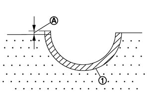
A : Crush height Standard : There must be crush height. - If the standard is not met, replace main bearings.
CONNECTING ROD BEARING CRUSH HEIGHT- When connecting rod bearing cap is removed after being tightened to the specified torque with connecting rod bearings (1) installed, the tip end of bearing must protrude. Refer to Disassembly and Assembly (GT-R certified NISSAN dealer) for the tightening procedure.
A : Crush height Standard : There must be crush height. - If the standard is not met, replace connecting rod bearings.
LOWER CYLINDER BLOCK BOLT OUTER DIAMETER- Measure the outer diameters (c), (d) at two positions as shown in the figure.
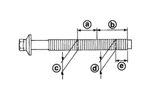
a : 20 mm (0.79 in) b : 30 mm (1.18 in) e : 10 mm (0.39 in) - If reduction appears in (a) range, regard it (c).
Limit [(d) – (c)] : 0.11 mm (0.0043 in) - If it exceeds the limit (large difference in dimensions), replace lower cylinder block bolt with new one.
FLYWHEEL- Check signal plate (A) and ring gear (B) for deformation or damage.
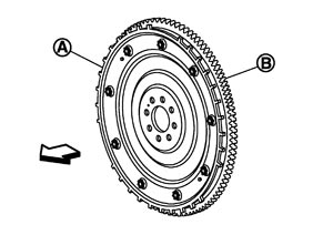
: Engine front ■ CAUTION ■- Never disassemble flywheel.
- Never place flywheel with signal plate facing down.
- When handling signal plate, take care not to damage or scratch it.
- Handle signal plate in a manner that prevents it from becoming magnetized.
- Never disassemble flywheel.
- If anything is found, replace flywheel.
OIL JET- Check nozzle for deformation and damage.
- Blow compressed air from nozzle, and check for clogs.
- If it is not satisfied, clean or replace oil jet.
OIL JET RELIEF VALVE- Using a clean plastic stick, press check valve in oil jet relief valve. Check that valve moves smoothly with proper reaction force.
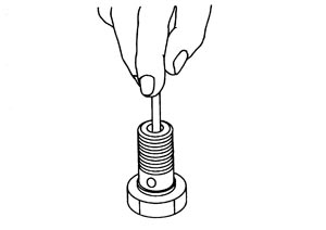
- If it is not satisfied, replace oil jet relief valve.