SECONDARY AIR INJECTION SYSTEM
Exploded View
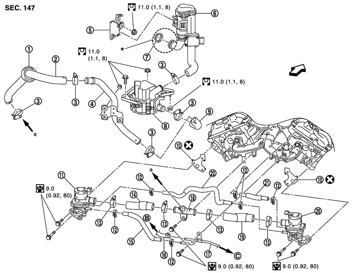
|
1. |
Rubber |
2. |
Air pump hose |
3. |
Clamp |
|
4. |
Air pump pipe |
5. |
Air pump cleaner bracket |
6. |
Air pump cleaner assembly |
|
7. |
Collar |
8. |
Air pump assembly |
9. |
Air pump hose |
|
10. |
Gasket |
11. |
Air cut solenoid valve (bank 2) |
12. |
Clamp |
|
13. |
Clamp |
14. |
Air hose |
15. |
Water hose |
|
16. |
Water hose |
17. |
Water outlet tube |
18. |
3-WAY hose connector |
|
19. |
Air hose |
20. |
Air cut solenoid valve (bank 1) |
21. |
Water hose |
|
22. |
Water hose |
|
|
|
|
|
B. |
To heater pipe |
C. |
To exhaust manifold and turbocharger assembly (bank 1) |
|
|

|
: Engine front |
|
|
|
|
|
Refer to Components for symbols in the figure. |
|||||
■ CAUTION ■
An air cut solenoid valve malfunction may cause a backflow of exhaust gas. Therefore, install pipes with the utmost caution. Special cautions are required for installing the parts marked with an asterisk (*) shown in the exploded view. (Check that the collar pawl is thoroughly fit.)
Removal and Installation
 REMOVAL
- 1.Remove battery. Refer to Exploded View.
- 2.Remove fender protector (rear). Refer to Exploded View.
- 3.Disconnect air pump hose at 3-way hose connector side.
- Mark with paint for a reference purpose before removal.
■ CAUTION ■
When removing hoses, never apply excessive force to prevent parts (e.g. 3-way hose connector) from damage.- 4.Remove cowl top cover (RH). Refer to Exploded View.
- 5.Remove air pump assembly and air pump cleaner assembly, disconnecting each joints.
- Mark with paint for a reference purpose before removal.■ CAUTION ■
- Handle carefully to avoid any shock to air pump assembly and air pump cleaner assembly.
- Never disassemble air pump assembly and air pump cleaner assembly.
- Handle carefully to avoid any shock to air pump assembly and air pump cleaner assembly.
- 6.Remove the following part before removing the air cut solenoid valve:
- Intake manifold collector: Refer to Exploded View.■ CAUTION ■Mark the parts with paint in advance of the reinstallation to prevent misalignment between the intake manifold collector and intake manifold.
- Heater pipe and heater hose: Refer to Exploded View (GT-R certified NISSAN dealer).
- Handle carefully to avoid any shock to air cut solenoid valve.
- Never disassemble air cut solenoid valve.
■ CAUTION ■
INSTALLATIONNote the following, and install in the reverse order of removal.
■ CAUTION ■
An air cut solenoid valve malfunction may cause a backflow of exhaust gas. Therefore, install pipes with the utmost caution. Special cautions are required for installing the parts marked with an asterisk (*) shown in the exploded view. (Check that the collar pawl is thoroughly fit.)- Align marks. Attach each joint. Screw clamps firmly.
Clamp tightening torque  : 1.85 N·m (0.19 kg-m, 16 in-lb)■ CAUTION ■Never use air tool or power tools for tightening.