AWD CONTROL UNIT
TRANSFER
Reference Value
 VALUES ON THE DIAGNOSIS TOOL
|
Monitor item |
Condition |
Value/Status | |
| STOP LAMP SW | Brake pedal: Depressed | On | |
| Brake pedal: Released | Off | ||
| ENG SPEED SIG | Engine stopped (Engine speed: Less than 400 rpm) | Stop | |
| Engine running (Engine speed: 400 rpm or more) | Run | ||
| ETS ACTUATOR | Engine stopped (Ignition switch: ON) | Off | |
| Engine running | On | ||
| 4WD WARN LAMP | AWD warning lamp: ON | On | |
| AWD warning lamp: OFF | Off | ||
| 4WD MODE SW | Always | ## | |
| 4WD MODE MON | Engine running | AUTO | |
| DIS-TIRE MONI | Vehicle running with normal size tire installed | 0 – 4 mm | |
| Vehicle running with improper size tire installed (Front/rear tire size difference, wear condition) | 4 – 8 mm, 8 – mm | ||
| P BRAKE SW | Parking brake operated | On | |
| Parking brake not operated | Off | ||
| BATTERY VOLT | Always | Battery voltage | |
| THRTL POS SEN | When depressing accelerator pedal (Value rises gradually in response to throttle position.) | 0 – 100% | |
| ETS SOLENOID | Engine running
| Approx. 0.000 A | |
Engine running
| Approx. 0.000 – 0.500 A* | ||
| FR RH SENSOR | Vehicle stopped | 0.00 km/h (0.00 mph) | |
| Vehicle running ■ CAUTION ■ Check air pressure of tire under standard condition. | Approx. equal to the indication on speedometer (Inside of ±10%) | ||
| FR LH SENSOR | Vehicle stopped | 0.00 km/h (0.00 mph) | |
| Vehicle running ■ CAUTION ■ Check air pressure of tire under standard condition. | Approx. equal to the indication on speedometer (Inside of ±10%) | ||
| RR RH SENSOR | Vehicle stopped | 0.00 km/h (0.00 mph) | |
| Vehicle running ■ CAUTION ■ Check air pressure of tire under standard condition. | Approx. equal to the indication on speedometer (Inside of ±10%) | ||
| RR LH SENSOR | Vehicle stopped | 0.00 km/h (0.00 mph) | |
| Vehicle running ■ CAUTION ■ Check air pressure of tire under standard condition. | Approx. equal to the indication on speedometer (Inside of ±10%) | ||
TERMINAL LAYOUT PHYSICAL VALUES
|
Terminal No. (Wire color) |
Description |
Condition |
Value (Approx.) |
|||
|
+ |
- |
Signal name |
Input/Output |
|||
|
1 (R) |
Ground |
AWD solenoid power supply |
Output |
Engine speed: At idle |
0 V |
|
|
Engine speed: 3,000 rpm or more constant |
2.5 V* |
|||||
|
2 (G) |
Ground |
AWD solenoid ground |
— |
Engine speed: At idle |
0 V |
|
|
Engine speed: 3,000 rpm or more constant |
0 V |
|||||
|
7 (W) |
Ground |
Ignition switch |
Input |
Ignition switch: ON |
Battery voltage |
|
|
Ignition switch: OFF |
0 V |
|||||
|
8 (L) |
— |
CAN-H |
Input/Output |
— |
— |
|
|
9 (Y) |
Ground |
Power supply (AWD solenoid) |
Input |
Always |
Battery voltage |
|
|
10 (B) |
Ground |
Ground |
— |
Always |
0 V |
|
|
11 (B) |
Ground |
Ground |
— |
Always |
0 V |
|
|
16 (P) |
— |
CAN-L |
Input/Output |
— |
— |
|
Wiring Diagram - AWD SYSTEM -
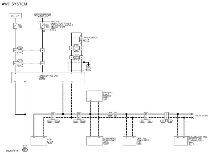
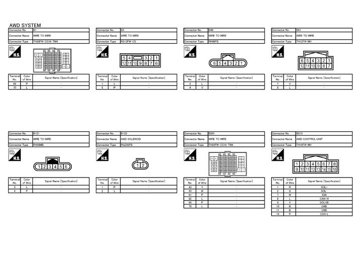
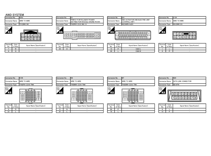
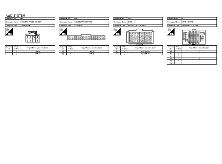
Fail-Safe
AWD system- If any malfunction occurs in AWD electrical system, and control unit detects the malfunction, AWD warning lamp on combination meter turns ON to indicate system malfunction.
- When AWD warning lamp is ON, vehicle changes to rear-wheel drive or shifts to 4-wheel drive (front-wheels still have some driving torque).
- AWD system activates its protection function (shuts down AWD system temporarily) if AWD system detects high load continuously or the front wheel tire size differs from the rear tire size. (AWD system is automatically restored if AWD system no longer detects any overload or the tire size difference is eliminated.)
|
Mode |
Warning lamp |
DTC |
Detected area (Error area) |
Error area and root cause |
|
|
Protection function |
Blinking*1 |
— |
AWD control unit |
Transfer assembly in protection mode. It is not malfunction. (Internal temperature rise of electric controlled coupling) |
|
|
Blinking*2 |
— |
Outer diameters of front and rear wheel tires |
Malfunction in each tire or different tire diameter |
||
|
Fail-safe |
ON |
C1201 |
AWD control unit |
Internal malfunction of AWD control unit |
|
|
C1203 |
ABS actuator and electric unit (control unit) |
ABS malfunction
|
|||
|
C1204 |
AWD solenoid |
Internal malfunction of electric controlled coupling |
|||
|
C1205 |
AWD control unit |
Internal malfunction of AWD control unit |
|||
|
C1210 |
ECM |
Malfunction of engine control system
|
|||
|
ON |
U1000 |
CAN communication line |
|
||
|
U1010 |
AWD control unit |
Malfunction of AWD control unit |
|||
DTC Inspection Priority Chart
If some DTCs are displayed at the same time, perform inspections one by one based on the following priority chart.
| Priority | Detected items (DTC) |
| 1 |
|
| 2 |
|
| 3 |
|
| 4 |
|
DTC Index
|
DTC |
Display Items |
Reference |
|
|
C1201 |
CONTROLLER FAILURE |
DTC Logic (GT-R certified NISSAN dealer)
|
|
|
C1203 |
ABS SYSTEM |
DTC Logic (GT-R certified NISSAN dealer)
|
|
|
C1204 |
4WD SOLENOID |
DTC Logic (GT-R certified NISSAN dealer)
|
|
|
C1205 |
4WD ACTUATOR RLY |
DTC Logic (GT-R certified NISSAN dealer)
|
|
|
C1210 |
ENGINE SIGNAL 1 |
DTC Logic (GT-R certified NISSAN dealer)
|
|
|
P1826 |
OIL TEMP SEN |
DTC Logic (GT-R certified NISSAN dealer)
|
|
|
U1000 |
CAN COMM CIRCUIT |
DTC Logic (GT-R certified NISSAN dealer)
|
|
|
U1010 |
CONTROL UNIT (CAN) |
DTC Logic (GT-R certified NISSAN dealer)
|
|