SIDE SHAFT
FRONT FINAL DRIVE: F160A
Exploded View
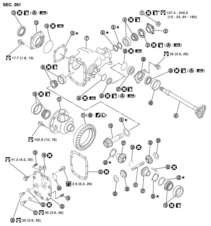
|
1. |
Drive pinion lock nut |
2. |
Companion flange |
3. |
Front oil seal |
|
4. |
Pinion front bearing |
5. |
Drive pinion bearing adjusting washer |
6. |
Drive pinion adjusting washer |
|
7. |
Gear carrier |
8. |
Pinion rear bearing |
9. |
Pinion height adjusting washer |
|
10. |
Drive pinion |
11. |
Drive gear |
12. |
Side oil seal (right side) |
|
13. |
Side retainer |
14. |
O-ring |
15. |
Side bearing adjusting shim |
|
16. |
Side bearing |
17. |
Differential case |
18. |
Breather connector |
|
19. |
Dowel pin |
20. |
Filler plug |
21. |
Drain plug |
|
22. |
Gasket |
23. |
Carrier cover |
24. |
Gear oil defense |
|
25. |
Gasket |
26. |
Side gear thrust washer |
27. |
Side gear |
|
28. |
Circular clip |
29. |
Pinion mate thrust washer |
30. |
Pinion mate gear |
|
31. |
Pinion mate shaft |
32. |
Lock pin |
33. |
Side bearing adjusting washer |
|
34. |
O-ring |
35. |
Side oil seal (left side) |
36. |
O-ring |
|
37. |
Side shaft bearing |
38. |
Extension tube retainer |
39. |
Side shaft oil seal |
|
40. |
Dust seal |
41. |
Side shaft |
|
|
|
A: |
Oil seal lip |
B: |
Screw hole |
|
|
 : Apply gear oil. Refer to Fluids and Lubricants. : Apply gear oil. Refer to Fluids and Lubricants. |
|||||
 : Apply anti-corrosion oil. : Apply anti-corrosion oil. |
|||||

 : Apply Genuine Medium Strength Thread Locking Sealant or equivalent. Refer to Recommended Chemical Products and Sealants. : Apply Genuine Medium Strength Thread Locking Sealant or equivalent. Refer to Recommended Chemical Products and Sealants. |
|||||
|
Refer to Components for symbols not described above. |
|||||
Disassembly
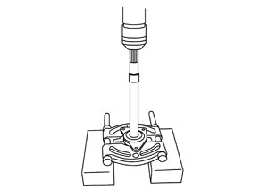
- 1.Hold extension tube retainer with puller, then press out side shaft using a press.
- 2.Remove side shaft oil seal (1) from extension tube retainer with a flat- blade screwdriver.
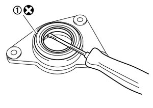
■ CAUTION ■
Never damage extension tube retainer.- 3.Remove side shaft bearing from extension tube retainer.
- 4.Remove O-ring from extension tube retainer.
- 5.Remove dust seal from side shaft.
Assembly
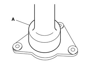
- 1.Using the drift (A) [SST: KV38100200 ( — )], install side shaft oil seal.
- Never reuse oil seal.
- When installing, never incline oil seal.
- Apply multi-purpose grease onto oil seal lips, and gear oil onto the circumference of oil seal.
■ CAUTION ■
- 2.Install dust seal.
- 3.Support side shaft bearing with the drift (A) [SST: ST30032000 (J-26010-01)], then press side shaft (1) into the side shaft bearing using a press.
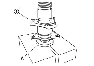
- 4.Apply multi-purpose grease to O-ring, and install it to extension tube retainer.
■ CAUTION ■
Never reuse O-ring.Inspection After Disassembly
 DRIVE GEAR AND DRIVE PINION
- Clean up the disassembled parts.
- If the gear teeth never mesh or line-up correctly, determine the cause and adjust or replace as necessary.
- If the gears are worn, cracked, damaged, pitted or chipped (by friction) noticeably, replace with new drive gear and drive pinion as a set.
BEARING- Clean up the disassembled parts.
- If any chipped (by friction), pitted, worn, rusted or scratched marks, or unusual noise from the bearing is observed, replace as a bearing assembly (as a new set).
SIDE GEAR AND PINION MATE GEAR- Clean up the disassembled parts.
- If any cracks or damage on the surface of the tooth is found, replace.
- If any worn or chipped mark on the contact sides of the thrust washer is found, replace.
SIDE GEAR THRUST WASHER AND PINION MATE THRUST WASHER- Clean up the disassembled parts.
- If it is chipped (by friction), damaged, or unusually worn, replace.
OIL SEAL- Whenever disassembled, replace.
- If wear, deterioration of adherence (sealing force lips), or damage is detected on the lips, replace them.
DIFFERENTIAL CASE- Clean up the disassembled parts.
- If any wear or crack on the contact sides of the differential case is found, replace.
COMPANION FLANGE- Clean up the disassembled parts.
- If any chipped mark [about 0.1 mm, (0.004 in)] or other damage on the contact sides of the lips of the companion flange is found, replace.