DIFFERENTIAL ASSEMBLY
FRONT FINAL DRIVE: F160A
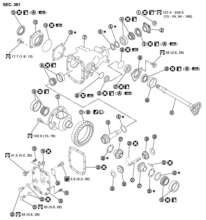
Exploded View
|
1. |
Drive pinion lock nut |
2. |
Companion flange |
3. |
Front oil seal |
|
4. |
Pinion front bearing |
5. |
Drive pinion bearing adjusting washer |
6. |
Drive pinion adjusting washer |
|
7. |
Gear carrier |
8. |
Pinion rear bearing |
9. |
Pinion height adjusting washer |
|
10. |
Drive pinion |
11. |
Drive gear |
12. |
Side oil seal (right side) |
|
13. |
Side retainer |
14. |
O-ring |
15. |
Side bearing adjusting shim |
|
16. |
Side bearing |
17. |
Differential case |
18. |
Breather connector |
|
19. |
Dowel pin |
20. |
Filler plug |
21. |
Drain plug |
|
22. |
Gasket |
23. |
Carrier cover |
24. |
Gear oil defense |
|
25. |
Gasket |
26. |
Side gear thrust washer |
27. |
Side gear |
|
28. |
Circular clip |
29. |
Pinion mate thrust washer |
30. |
Pinion mate gear |
|
31. |
Pinion mate shaft |
32. |
Lock pin |
33. |
Side bearing adjusting washer |
|
34. |
O-ring |
35. |
Side oil seal (left side) |
36. |
O-ring |
|
37. |
Side shaft bearing |
38. |
Extension tube retainer |
39. |
Side shaft oil seal |
|
40. |
Dust seal |
41. |
Side shaft |
|
|
|
A: |
Oil seal lip |
B: |
Screw hole |
|
|
 : Apply gear oil. Refer to Fluids and Lubricants. : Apply gear oil. Refer to Fluids and Lubricants. |
|||||
 : Apply anti-corrosion oil. : Apply anti-corrosion oil. |
|||||

 : Apply Genuine Medium Strength Thread Locking Sealant or equivalent. Refer to Recommended Chemical Products and Sealants. : Apply Genuine Medium Strength Thread Locking Sealant or equivalent. Refer to Recommended Chemical Products and Sealants. |
|||||
|
Refer to Components for symbols not described above. |
|||||
Disassembly
- 1.Drain gear oil, if necessary.
- 2.Remove carrier cover mounting bolts.
- 3.Remove carrier cover from gear carrier by tapping carrier cover with plastic hammer.
- Never damage the carrier cover and gear carrier.
■ CAUTION ■
- 4.Remove side retainer.
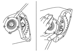
- 5.Remove side bearing adjusting shim.
- 6.Remove O-ring from side retainer.
- 7.Remove differential case assembly from gear carrier.
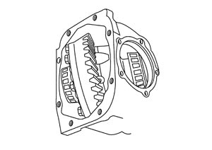
- 8.Remove side oil seal (right side) from side retainer.
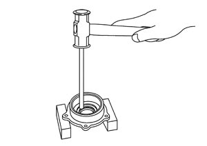
- 9.Remove side bearing outer race with puller (A) [SST: KV381054S0 (J-34286)].
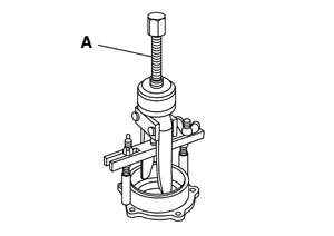
- 10.Remove O-ring from gear carrier.
- 11.Remove side oil seal (left side) from gear carrier.
- 12.Remove side bearing outer race with puller (A) [SST: KV381054S0 (J-34286)].
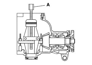
- 13.Remove side bearing inner race.
- To prevent damage to the side bearing and drive gear, place copper plates between these parts and vise.
- It is not necessary to remove side bearing inner race except if it is replaced.
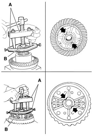
To prevent damage to bearing, engage puller jaws in groove (
 ).
).| A: Puller [SST: ST33051001 (J-22888-20)] | |
| B: Base [SST: ST33061000 (J-8107-2)] |
■ CAUTION ■
- 14.For proper reinstallation, paint matching marks on one differential case assembly.
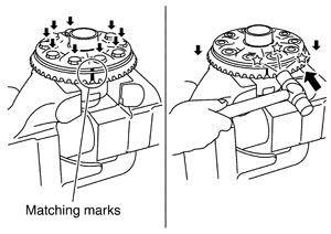
■ CAUTION ■
For matching marks, use paint. Never damage differential case and drive gear.- 15.Remove drive gear mounting bolts.
- 16.Tap drive gear off differential case assembly with a soft hammer.
■ CAUTION ■
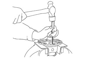
Tap evenly all around to keep drive gear from bending.- 17.Remove lock pin of pinion mate shaft with a punch from drive gear side.
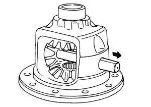
- 18.Remove pinion mate shaft.
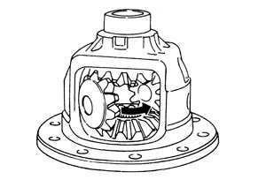
- 19.Turn pinion mate gear, then remove pinion mate gears, pinion mate thrust washers, side gears and side gear thrust washers from differential case.
Assembly
- 1.Install side gear thrust washers with the same thickness as the ones installed prior to disassembly or reinstall the old ones on the side gears.
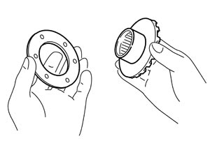
- 2.Install side gears and thrust washers into differential case.
- Never reuse circular clip.
- Make sure that the circular clip is installed to side gear (side retainer side).
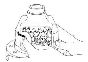
■ CAUTION ■
- 3.Align 2 pinion mate gears in diagonally opposite positions, then rotate and install them into differential case after installing thrust washer to pinion mate gear.
- 4.Align the lock pin holes on differential case with shaft, and install pinion mate shaft.
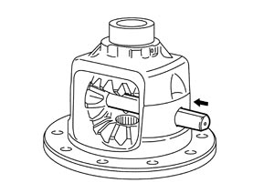
- 5.Measure side gear end play. If necessary, select the appropriate side gear thrust washers.
-
(1)Place differential case straight up so that side gear to be measured comes upward.
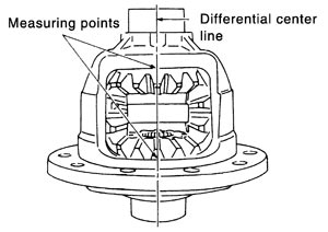
-
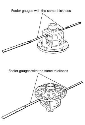
(2)Using feeler gauge, measure the clearance between side gear back and differential case at 3 different points, while rotating side gear. Average the 3 readings, and then measure the clearance of the other side as well.
| Standard | |
| Side gear back clearance | : Refer to Differential Side Gear Clearance (GT-R certified NISSAN dealer). |
■ CAUTION ■
To prevent side gear from tilting, insert feeler gauges with the same thickness from both sides.-
(3)If the back clearance is outside the specification, use a thicker/thinner side gear thrust washer to adjust.
| When the back clearance is large: | Use a thicker thrust washer. |
| When the back clearance is small: | Use a thinner thrust washer. |
■ CAUTION ■
Select a side gear thrust washer for right and left individually.- 6.Drive a lock pin into pinion mate shaft, using a punch.
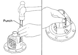
Make sure lock pin is flush with differential case.
■ CAUTION ■
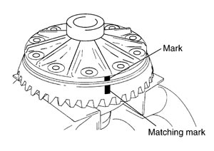
Never reuse lock pin.- 7.Align the matching mark of drive gear with the mark of differential case, then place drive gear.
- 8.Apply thread locking sealant into the thread hole of drive gear.
- Use Genuine Medium Strength Thread Locking Sealant or equivalent. Refer to Recommended Chemical Products and Sealants.
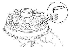
■ CAUTION ■
Drive gear back and threaded holes must be cleaned and degreased sufficiently.- 9.Install drive gear on the mounting bolts.
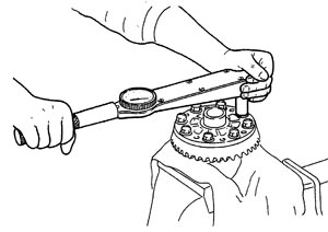
■ CAUTION ■
Tighten bolts in a crisscross fashion.- 10.Press side bearing inner races to differential case, using the drift and the base.
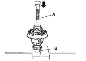
| A: Drift [SST: ST33230000 (J-25805-01)] | |
| B: Base [SST: ST33061000 (J-8107-2)] |
■ CAUTION ■
Never reuse side bearing inner race.- 11.Press-fit side bearing outer race into side retainer with the drift and the drift bar.
- At first, using a hammer, tap bearing outer race until it becomes flat to side retainer.
- Never reuse side bearing outer race.
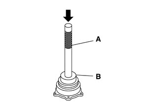
| A: Drift bar [SST: ST30611000 (J-25742-1)] | |
| B: Drift [SST: KV31103000 (J-38982)] |
■ CAUTION ■
- 12.Press-fit side bearing outer race into gear carrier with the drift and the drift bar.
- At first, using a hammer, tap bearing outer race until it becomes flat to gear carrier.
- Never reuse side bearing outer race.
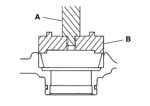
| A: Drift bar [SST: ST30611000 (J-25742-1)] | |
| B: Drift [SST: KV31103000 (J-38982)] |
■ CAUTION ■
- 13.Place the differential case assembly into gear carrier.
- 14.Measure side bearing preload. If necessary, select the appropriate side bearing adjusting shim. Refer to Adjustment.
- 15.Install selected side bearing adjusting shim (1). Refer to Adjustment.
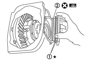
- 16.Apply multi-purpose grease to O-ring (2), and install it to side retainer.
■ CAUTION ■
Never reuse O-ring.- 17.Install side retainer assembly to gear carrier.
- 18.Install side retainer mounting bolts.
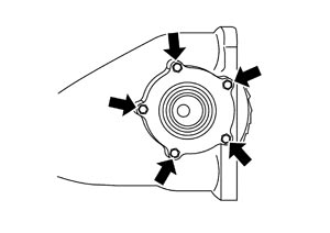
- 19.Using the drift (A) [SST: ST33400001 (J-26082)], press-fit side oil seal so that its surface comes face‐to‐face with the end surface of the side retainer.
- Never reuse oil seal.
- When installing, never incline oil seal.
- Apply multi-purpose grease onto oil seal lips, and gear oil onto the circumference of oil seal.
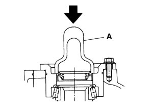
■ CAUTION ■
- 20.Using the drift (A) [SST: KV38102100 (J-25803-01)], press-fit side oil seal so that its surface comes face-to-face with the end surface of gear carrier.
- Never reuse oil seal.
- When installing, never incline oil seal.
- Apply multi-purpose grease onto oil seal lips, and gear oil onto the circumference of oil seal.
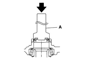
■ CAUTION ■
- 21.Apply multi-purpose grease to O-ring, and install it to gear carrier.
■ CAUTION ■
Never reuse O-ring.- 22.Check and adjust drive gear runout, tooth contact, drive gear to drive pinion backlash, and total preload torque. Refer to Adjustment.Recheck above items. Readjust as described above, if necessary.
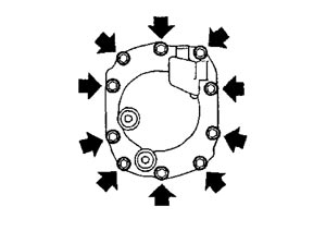
- 23.Install carrier cover and gasket on gear carrier and tighten mounting bolts.
- 24.Install the breather connector with the paint mark positioned toward the vehicle front.
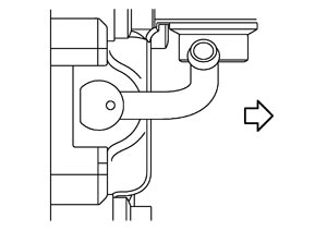
 : Vehicle front : Vehicle front |
■ CAUTION ■
Never reuse the air breather.Adjustment
 TOTAL PRELOAD TORQUE
- Before inspection and adjustment, drain gear oil.
- 1.Rotate drive pinion back and forth 2 to 3 times to check for unusual noise and rotation malfunction.
- 2.Rotate drive pinion at least 20 times to check for smooth operation of the bearing.
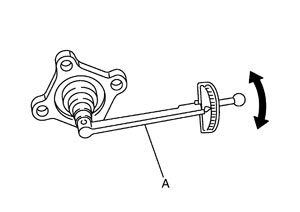
- 3.Measure total preload with preload gauge (A) [SST: ST3127S000 (J-25765-A)].
- If measured value is out of the specification, disassemble it to check and adjust each part. Adjust the pinion bearing preload and side bearing preload.Adjust the pinion bearing preload first, then adjust the side bearing preload.
| Standard | |
| Total preload torque | : Refer to Preload Torque (GT-R certified NISSAN dealer). |
NOTE:
Total preload torque = Pinion bearing preload torque + Side bearing preload torque| When the preload torque is large | |
| On pinion bearings: | Decrease the drive pinion bearing adjusting washer and drive pinion adjusting washer thickness. |
| On side bearings: | Increase the side bearing adjusting shim thickness. For select parts refer to parts information. |
| When the preload torque is small | |
| On pinion bearings: | Increase the drive pinion bearing adjusting washer and drive pinion adjusting washer thickness. |
| On side bearings: | Decrease the side bearing adjusting shim thickness. For select parts refer to parts information. |
SIDE BEARING PRELOAD- Before inspection and adjustment, drain gear oil.
- 1.Remove carrier cover and side retainer. Refer to Disassembly (GT-R certified NISSAN dealer).
- 2.Make sure all parts are clean. Also, make sure the bearings are well lubricated with gear oil.
- 3.Place the differential case assembly into gear carrier.
- 4.Install side bearing adjusting shim before disassembling or shim which thickness is the same as the one before disassembling.
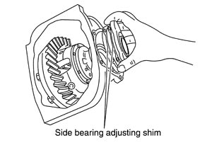
- 5.Install side retainer assembly to gear carrier.
■ CAUTION ■
Never install O-ring.- 6.Install side retainer mounting bolts to the specified torque.
- 7.Measure the turning torque of the gear carrier at the drive gear mounting bolts with a spring gauge [SST: — (J-8129)].
| Specification | : 34.2 – 39.2 N (3.5 – 4.0 kg, 7.7 – 8.8 lb) of pulling force at the drive gear bolt |
- 8.If the turning torque is outside the specification, use a thicker/thinner side bearing adjusting shim to adjust.
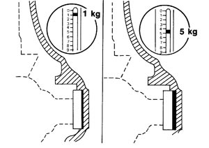
| If the turning torque is less than the specified range: | |
| Decrease the side bearing adjusting shim thickness. | |
| If the turning torque is greater than the specification: | |
| Increase the side bearing adjusting shim thickness. | |
- 9.Record the total amount of shim thickness required for the correct carrier side bearing preload.
DRIVE GEAR RUNOUT- 1.Remove carrier cover. Refer to Disassembly (GT-R certified NISSAN dealer).
- 2.Fit a dial indicator to the drive gear back face.
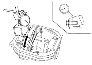
- 3.Rotate the drive gear to measure runout.
- If the runout is outside of the repair limit, check drive gear assembly condition; foreign material may be caught between drive gear and differential case, or differential case or drive gear may be deformed, etc.■ CAUTION ■Replace drive gear and drive pinion gear as a set.
| Limit | |
| Drive gear runout | : Refer to Drive Gear Runout (GT-R certified NISSAN dealer). |
TOOTH CONTACTBefore inspection and adjustment, drain gear oil.
- 1.Remove carrier cover. Refer to Disassembly (GT-R certified NISSAN dealer).
- 2.Apply red lead to drive gear.
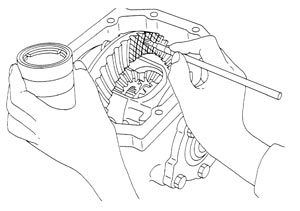
■ CAUTION ■
Apply red lead to both the faces of 3 to 4 gears at 4 locations evenly spaced on drive gear.- 3.Rotate drive gear back and forth several times, check drive pinion gear to drive gear tooth contact.
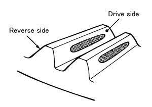
■ CAUTION ■
Check tooth contact on drive side and reverse side.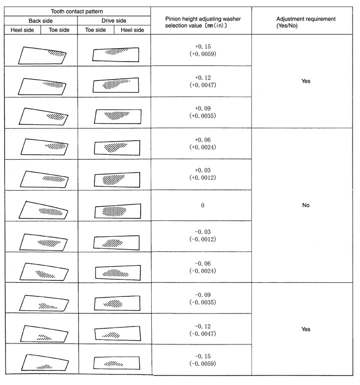
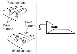
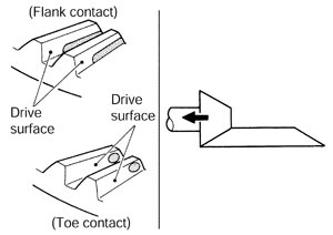
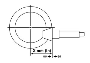
- 4.If tooth contact is improperly adjusted, follow the procedure below to adjust the pinion height [dimension (X)].
- If the tooth contact is near the face (face contact), or near the heel (heel contact), thicken pinion height adjusting washers to move drive pinion closer to drive gear.
- If the tooth contact is near the flank (flank contact), or near the toe (toe contact), thin pinion height adjusting washers to move drive pinion farther from drive gear.
 BACKLASH
Before inspection and adjustment, drain gear oil.
- 1.Remove carrier cover. Refer to Disassembly (GT-R certified NISSAN dealer).
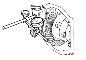
- 2.Fit a dial indicator to the drive gear face to measure the backlash.
- If the backlash is outside of the specified value, change the thickness of side bearing adjusting washer.
When the backlash is large: Decrease side bearing adjusting washer thickness. When the backlash is small: Increase side bearing adjusting washer thickness.
| Standard | |
| Backlash | : Refer to Backlash (GT-R certified NISSAN dealer). |
Inspection After Disassembly
DRIVE GEAR AND DRIVE PINION- Clean up the disassembled parts.
- If the gear teeth never mesh or line-up correctly, determine the cause and adjust or replace as necessary.
- If the gears are worn, cracked, damaged, pitted or chipped (by friction) noticeably, replace with new drive gear and drive pinion as a set.
BEARING- Clean up the disassembled parts.
- If any chipped (by friction), pitted, worn, rusted or scratched marks, or unusual noise from the bearing is observed, replace as a bearing assembly (as a new set).
SIDE GEAR AND PINION MATE GEAR- Clean up the disassembled parts.
- If any cracks or damage on the surface of the tooth is found, replace.
- If any worn or chipped mark on the contact sides of the thrust washer is found, replace.
SIDE GEAR THRUST WASHER AND PINION MATE THRUST WASHER- Clean up the disassembled parts.
- If it is chipped (by friction), damaged, or unusually worn, replace.
OIL SEAL- Whenever disassembled, replace.
- If wear, deterioration of adherence (sealing force lips), or damage is detected on the lips, replace them.
DIFFERENTIAL CASE- Clean up the disassembled parts.
- If any wear or crack on the contact sides of the differential case is found, replace.
COMPANION FLANGE- Clean up the disassembled parts.
- If any chipped mark [about 0.1 mm, (0.004 in)] or other damage on the contact sides of the lips of the companion flange is found, replace.