REPLACEMENT OPERATIONS
- Description
- Hoodledge Panel and Front Side Member
- Front Side Member
- Front Side Member (Partial Replacement)
- Front Pillar
- Outer Sill (Partial Replacement)
- Outer Sill
- Rear Fender
- Lock Pillar Reinforcement
- Outer Rear Wheelhouse
- Rear Panel
- Rear Floor Rear
- Rear Side Member
- Rear Side Member Extension
- Roof
- Seatback Support
Description
- This section is prepared for technicians who have attained a high level of skill and experience in repairing collision-damaged vehicles and also use modern service tools and equipment. Persons unfamiliar with body repair techniques should not attempt to repair collision-damaged vehicles by using this section.
- Technicians are also encouraged to read the Body Repair Manual (Fundamentals) in order to ensure that the original functions and quality of the vehicle are maintained. The Body Repair Manual (Fundamentals) contains additional information, including cautions and warnings, that are not including in this manual. Technicians should refer to both manuals to ensure proper repair.
- Please note that this information is prepared for worldwide usage, and as such, certain procedures might not apply in some regions or countries.
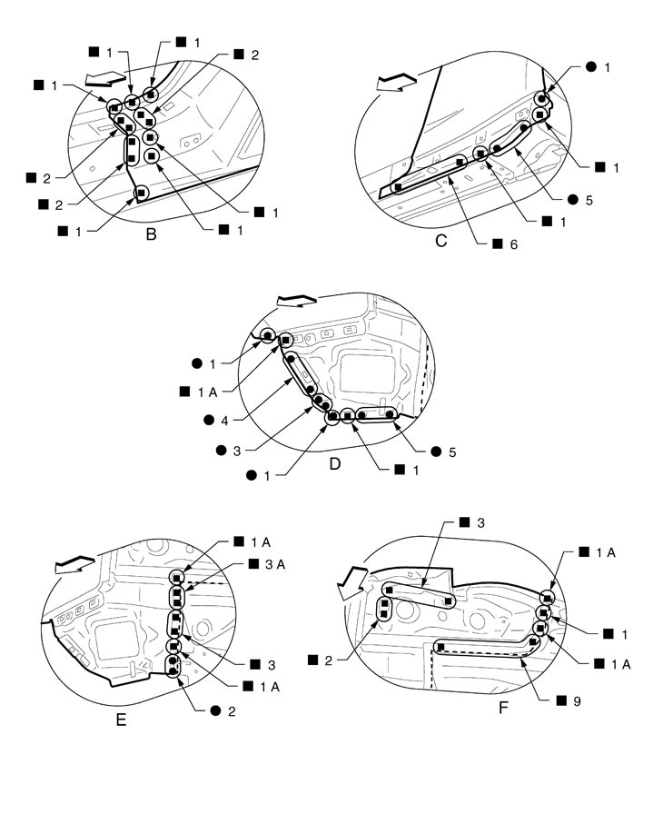
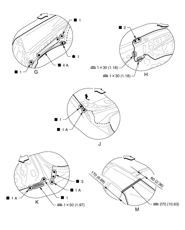
| Symbol marks | Description | |
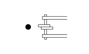 | 2-spot welds | 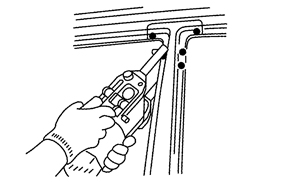 |
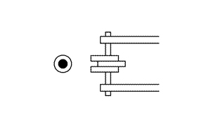 | 3-spot welds | |
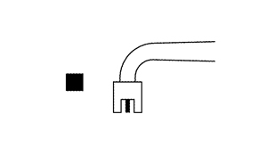 | MIG plug weld | 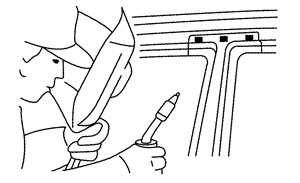 |
For 3 panels plug weld method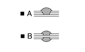 | ||
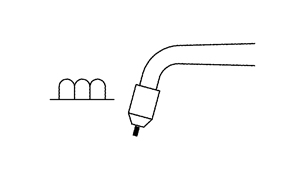 | MIG seam weld / Point weld | 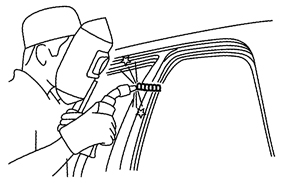 |
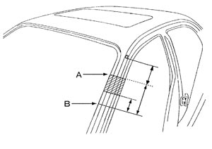
- Front pillar butt joint can be determined anywhere within shaded area as shown in the figure. The best location for the butt joint is at position A due to the construction of the vehicle.
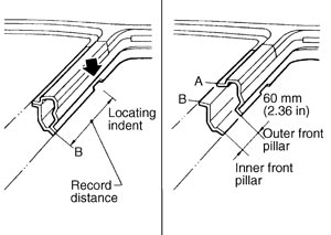
- Determine cutting position and record distance from the locating indent. Use this distance when cutting the service part. Cut outer front pillar over 60 mm (2.36 in) above the inner front pillar cut position.
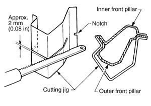
- Prepare a cutting jig to make outer pillar easier to cut. Also, this will permit the service part to be accurately cut at the joint position.
- An example of cutting operation using a cutting jig is as per the following.
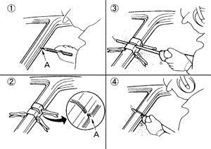
- Mark cutting lines.A: Cut position of outer pillarB: Cut position of inner pillar
- Align cutting line with notch on jig. Clamp jig to pillar.
- Cut outer pillar along groove of jig (at position A).
- Remove jig and cut remaining portions.
- Cut inner pillar at position B in same manner.
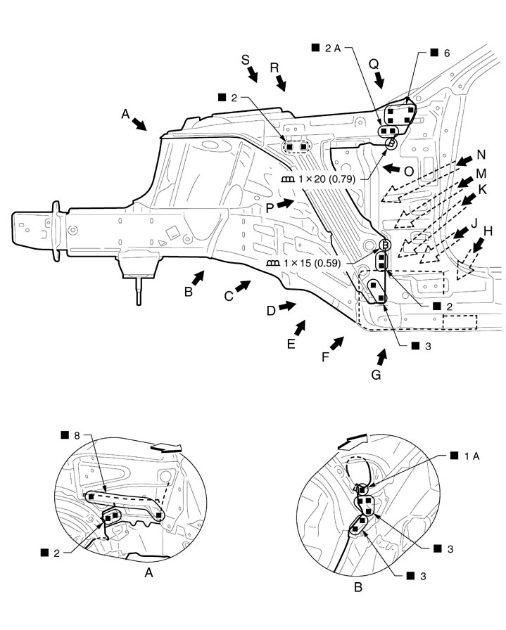
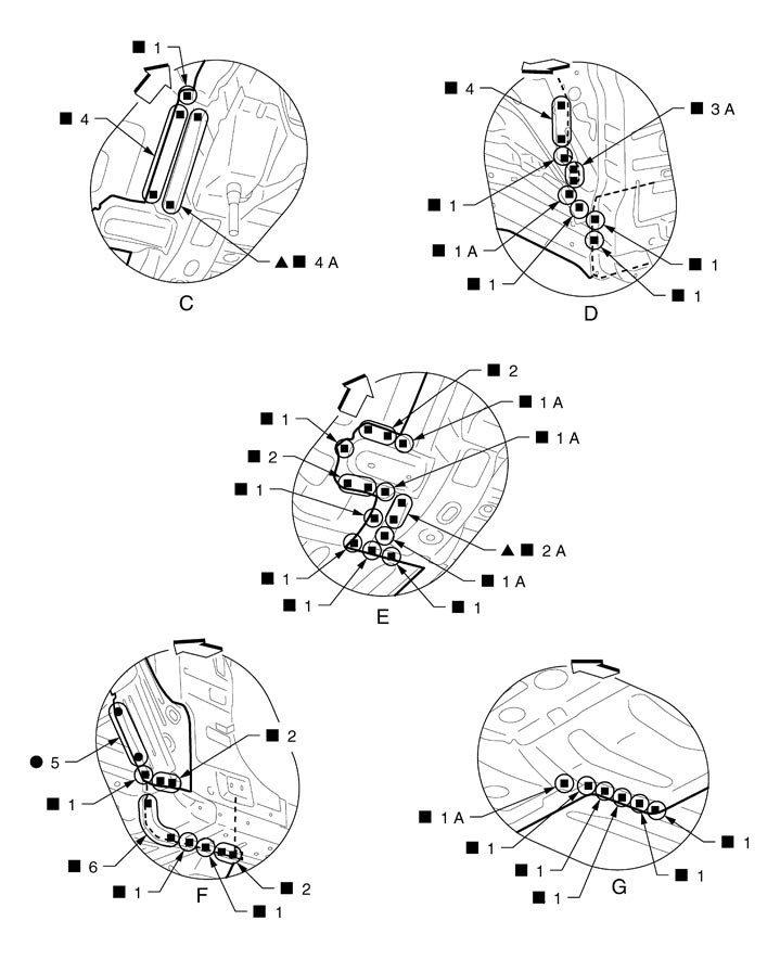
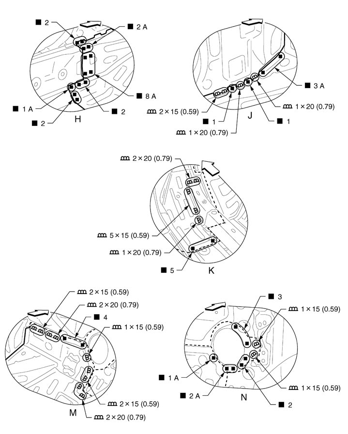
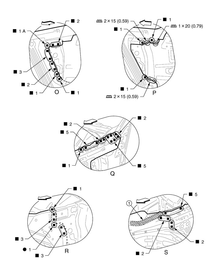
Hoodledge Panel and Front Side Member
■ CAUTION ■
Refer to ″Removal procedure of aluminum strut housing adhesive joint″ and ″Installation procedure of aluminum strut housing adhesive joint″ when replacing and reusing the hoodledge extension and hoodledge reinforcement.
|
Unit: mm (in) |
|
|
|
|
|

|
: Vehicle front |
|
|
|
|
|
Replacement parts |
|||||
|
• |
Front strut housing assembly with front side member (LH) |
• |
Hoodledge extension (LH) |
• |
Hoodledge reinforcement (LH) |
|
• |
Upper front hoodledge (LH) |
|
|
|
|
|
|
: Vehicle front |
|
|
|
|

|
: Drill φ9 mm (0.35 in) hole for the plug welding hole (ultra high strength steel plate). |
||||
|
Unit: mm (in) |
|
|
|
|
|
|
|
: Vehicle front |
|
|
|
|
|
1. |
Adhesive (3M™ Scotch-Weld™ Epoxy Adhesive DP420 Off-White Duo-Pak or equivalent) |
||||
|
Unit: mm (in) |
|
|
|
|
|
|
|
: Vehicle front |
|
|
|
|
View R: Before installing hoodledge reinforcement
View S: Cool the aluminum strut housing using compressed air to avoid the heat applied at the welding procedure.
 REMOVAL PROCEDURE OF ALUMINUM STRUT HOUSING ADHESIVE JOINT
■ CAUTION ■
- Always perform the following procedure to visually check the strut housing for deformation and perform the crack inspection (dye penetrant test) when the vehicle is damaged.
- Spray the cleaning solution on the inspection surface to clean the surface.
- Spray the penetrant liquid on the inspection surface and wait until the liquid has penetrates thoroughly.
- Wipe out any excess penetrant liquid on the inspection surface and then wipe out again with a cloth moistened by a little cleaning solution.
- Spray the developer on the inspection surface.
- A red indication appears on damaged area.
- Always use the specified bolt with its surface finished.
Never use bolts other than those that are specified, otherwise electric corrosion occurs. - Never reuse the removed specified bolts.
- Never use an impact wrench to remove or install the mounting bolt.
- Never remove the joint bolts (13) between side member and strut housing that are shown in the figure.
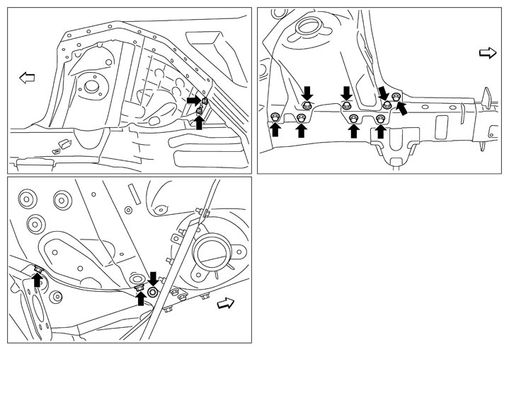
: Vehicle front 
: Never remove
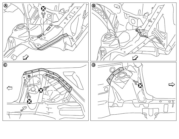
| A. | Hoodledge extension | B. | Hoodledge reinforcement | C. | Hoodledge extension, hoodledge reinforcement, and upper front hoodledge |
| D. | Front cowl top assembly | ||||
| : Vehicle front | ||||
 | : Adhesive exfoliated position | ||||
| Refer to ″How to use this manual″Components for the symbols shown in the figure. | |||||
- Remove the mounting bolts and spot welding of the hoodledge extension.
- Set the temperature gauge (the infrared non-contact temperature gauge is recommended for temperature management) to the strut housing, and then heat up to 110°C (230°F) using a halogen heater.■ CAUTION ■The heating temperature should not exceed 110°C (230°F).
- Use a chisel while heating the hoodledge extension, insert it between the hoodledge extension and the strut housing. Then slightly separate the hoodledge extension while ungluing the adhesive from the front.■ CAUTION ■Never damage the strut housing and the portions where the strut housing is bonded.
- Eliminate the adhesive that remains on the strut housing and the portions where the strut housing is bonded with a disc sander.
- If the coating on the joint surface with the strut housing and the vehicle is peeled off, apply epoxy primer on the surface to prevent electric corrosion.
- Remove the hoodledge reinforcement, upper front hoodledge, and front cowl top assembly while observing the procedure and precautions above.
INSTALLATION PROCEDURE OF ALUMINUM STRUT HOUSING ADHESIVE JOINT■ CAUTION ■
- Always use the specified bolt with its surface finished.
Never use bolts other than those that are specified, otherwise electric corrosion may occur. - Never reuse the removed specified bolts.
- Never use an impact wrench to remove or install the mounting bolt.
- Apply the adhesive, after degreasing its application area.
- Check the instruction manual of the adhesive for the hardening time.
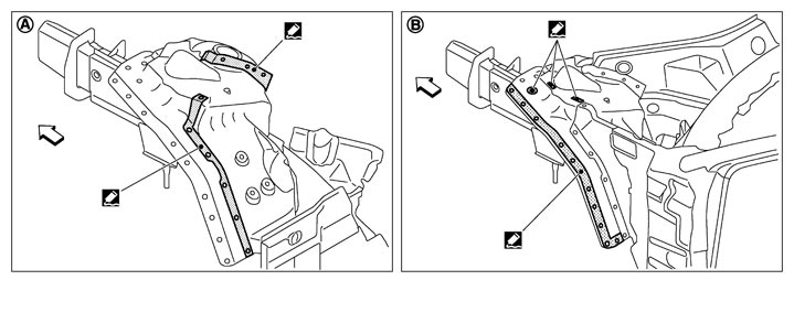
| A. | Bonded area between front cowl top assembly and upper front hoodledge | B. | Bonded area between hoodledge extension and hoodledge reinforcement | ||
| : Vehicle front | ||||
 | : 3M™ Scotch-Weld™ Epoxy Adhesive DP420 Off-White Duo-Pak or equivalent | ||||
| Refer to ″How to use this manual″Components for the symbols shown in the figure. | |||||
- Apply the adhesive to the bonded area (strut housing side) between front cowl top assembly (A) of strut housing and upper front hoodledge (A) before temporarily installing the service parts to the vehicle.■ CAUTION ■Apply the adhesive so that it protrudes from the bonded area (the flange end should be covered with the adhesive) when temporarily installing and tightening the service parts.
Add the adhesive to the area where the flange area is not covered with the adhesive. Then, smooth it with a spatula so that the flange end is covered with the adhesive.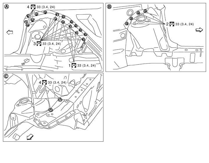
A. Joint with hoodledge extension, hoodledge reinforcement, and upper front hoodledge B. Joint with front cowl top assembly C. Joint with hoodledge extension : Vehicle front Refer to ″How to use this manual″Components for the symbols shown in the figure. - Temporarily install the parts before hardening the adhesive, tighten the mounting bolts of upper front hoodledge (1) and front cowl top assembly (2) evenly in 2 or 3 steps in the order shown in the figure, and then tighten bolts to the specified torque.
- Install hoodledge reinforcement (3) and hoodledge extension (4) in this order. Observe the procedure and precautions above.
Front Side Member
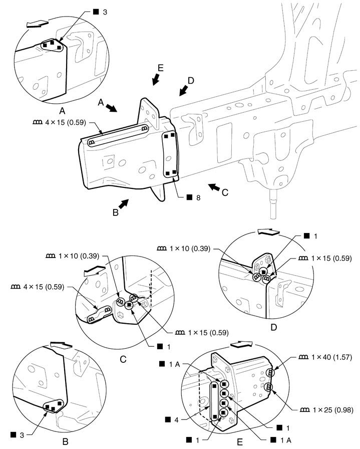
|
Unit: mm (in) |
|
|
|
|
|
|
|
: Vehicle front |
|
|
|
|
|
Replacement parts |
|||||
|
• |
Front side member (RH) |
• |
Front side member closing plate (RH) |
|
|
View A and B: Before installing front side member closing plate
Front Side Member (Partial Replacement)
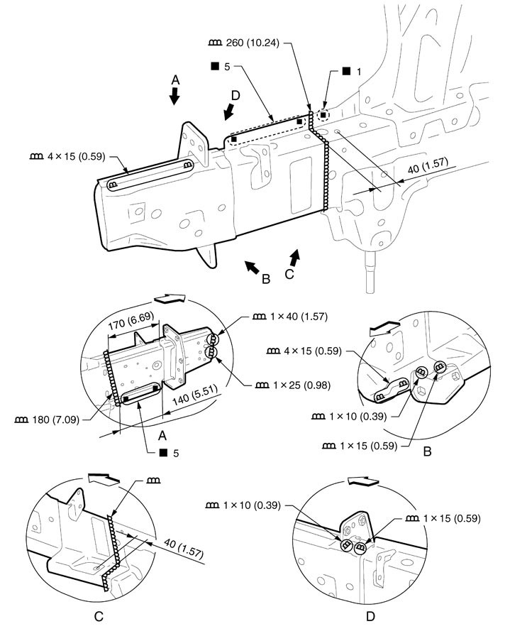
|
Unit: mm (in) |
|
|
|
|
|
|
|
: Vehicle front |
|
|
|
|
|
Replacement parts |
|
|
|
|
|
|
• |
Front side member (RH) |
• |
Front side member closing plate (RH) |
|
|
Front Pillar
Work after hoodledge reinforcement is removed.
■ CAUTION ■
Create the reinforcement sheet from the redundant area of service parts for butt welding area. Weld the reinforcing sheet on the back of butt welding area, and then perform butt welding. 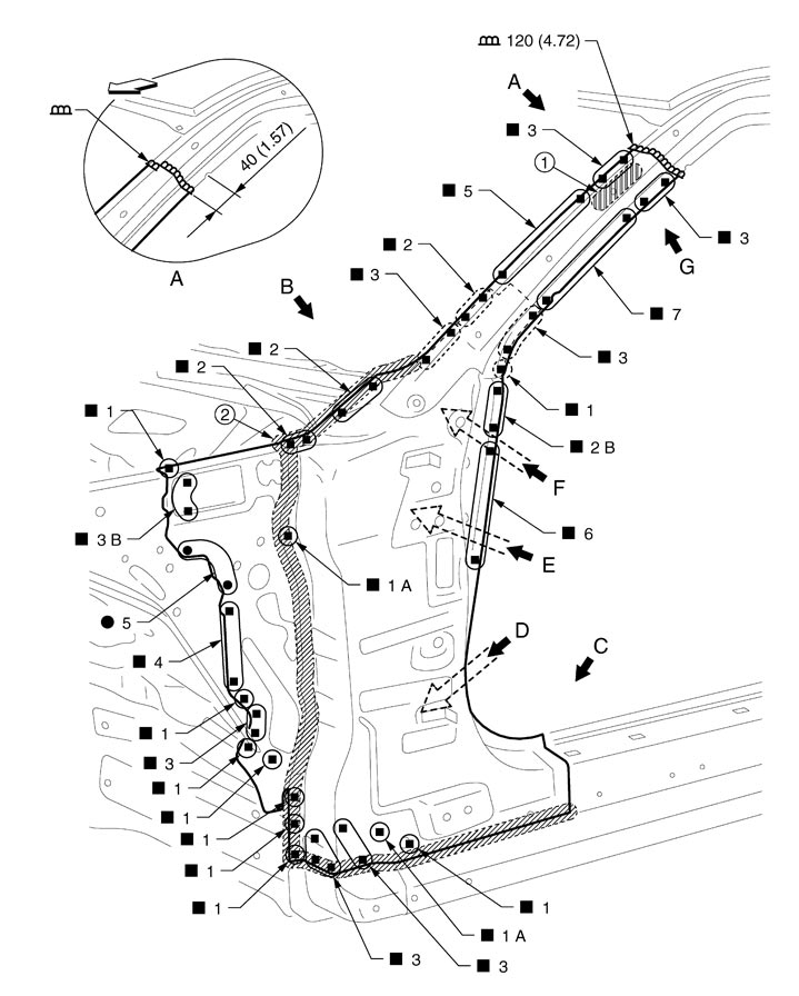
| 1. | Urethane foam | 2. | Body sealing | ||
| Unit: mm (in) | |||||
| : Vehicle front | ||||
| Replaced parts | |||||
| • | Side body assembly (LH) | • | Upper rear hoodledge (LH) | • | Inner side roof rail |
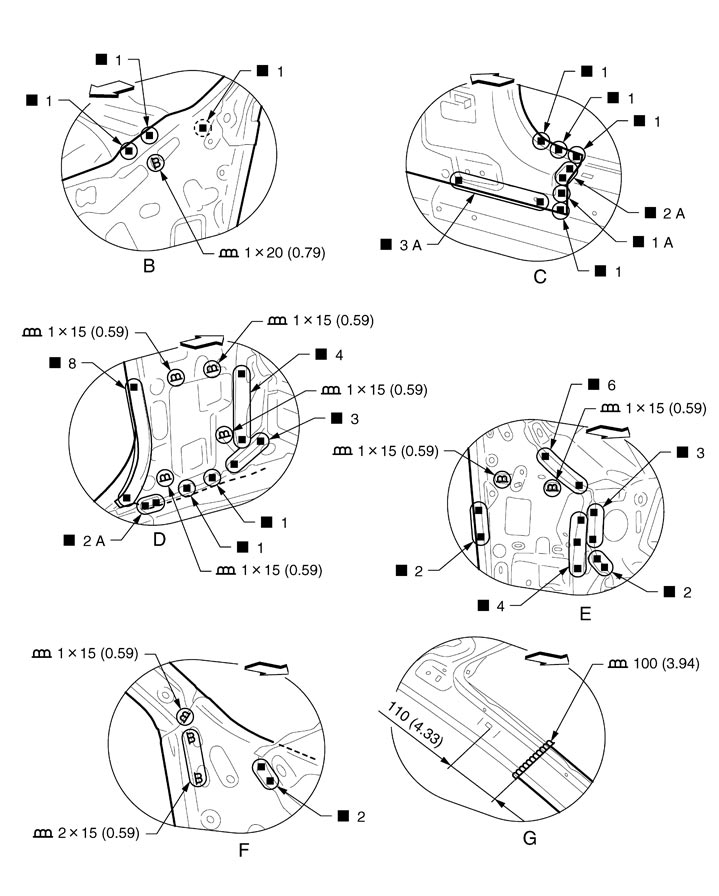
| Unit: mm (in) | |||||
| : Vehicle front | ||||
View B: Before installing side body assembly
Outer Sill (Partial Replacement)
■ CAUTION ■
Create the reinforcement sheet from the redundant area of service parts for butt welding area. Weld the reinforcing sheet on the back of butt welding area, and then perform butt welding.
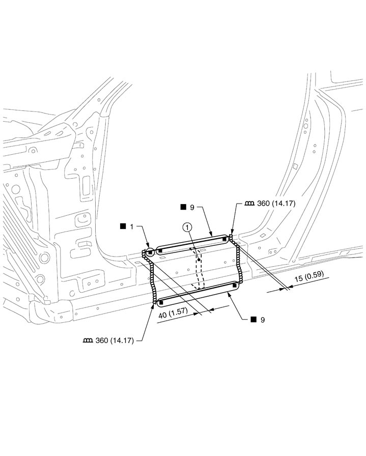
|
1. |
Outer sill brace |
|
|
|
|
|
Unit: mm (in) |
|
|
|
|
|
|
Replacement parts |
|||||
|
• |
Outer sill reinforcement (LH) |
|
|
|
|
Outer Sill
Work after hoodledge reinforcement, rear fender, and lock pillar reinforcement are removed.
Remove the front pillar brace (reusable).
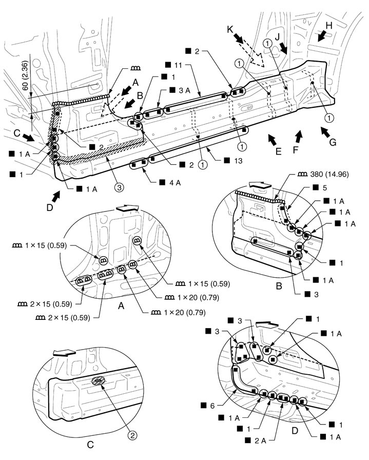
| 1. | Outer sill brace | 2. | Urethane foam | 3. | Body sealing |
| Unit: mm (in) | |||||
| : Vehicle front | ||||
| Replacement parts | |||||
| • | Outer sill reinforcement (LH) | ||||
View C: Before installing front pillar brace
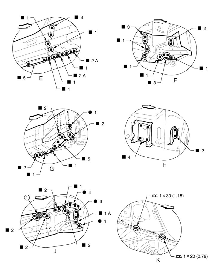
| 1. | Urethane foam | ||||
| Unit: mm (in) | |||||
| : Vehicle front | ||||
View H: Before installing outer sill reinforcement
Rear Fender
Perform the hidden welding point repair procedure for arrow view J by lifting up the flange of parcel shelf with rear waist.
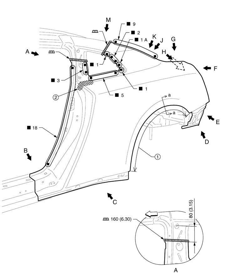
| 1. | Hemming | 2. | Urethane foam | ||
| Unit: mm (in) | |||||
| : Vehicle front | ||||
| Replacement parts | |||||
| • | Rear fender assembly (LH) | ||||
| : Vehicle front |
| Unit: mm (in) | |||||
| : Vehicle front | ||||
View J: The flange of parcel shelf with rear waist is lifted up.
POINT- Perform the hemming to the flange of wheelarch after applying the adhesive.
- Apply the sealing to the flange end.
- Refer to Rear Fender Hemming Process.
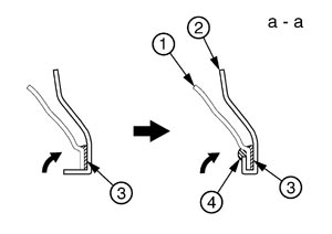
1. Rear wheel well outer 2. Rear fender 3. Adhesive 4. Sealing 1. Outer rear wheelhouse 2. Rear fender 3. Adhesive 4. Sealing
Lock Pillar Reinforcement
Work after rear fender is removed.
■ CAUTION ■
Create the reinforcement sheet from the redundant area of service parts for butt welding area. Weld the reinforcing sheet on the back of butt welding area, and then perform butt welding. 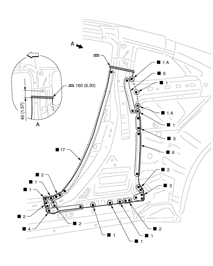
| Unit: mm (in) | |||||
| : Vehicle front | ||||
| Replacement parts | |||||
| • | Lock pillar reinforcement (LH) | ||||
Outer Rear Wheelhouse
Work after rear fender and lock pillar reinforcement are removed.
Remove the outer sill reinforcement rear and rear pillar reinforcement (reusable).
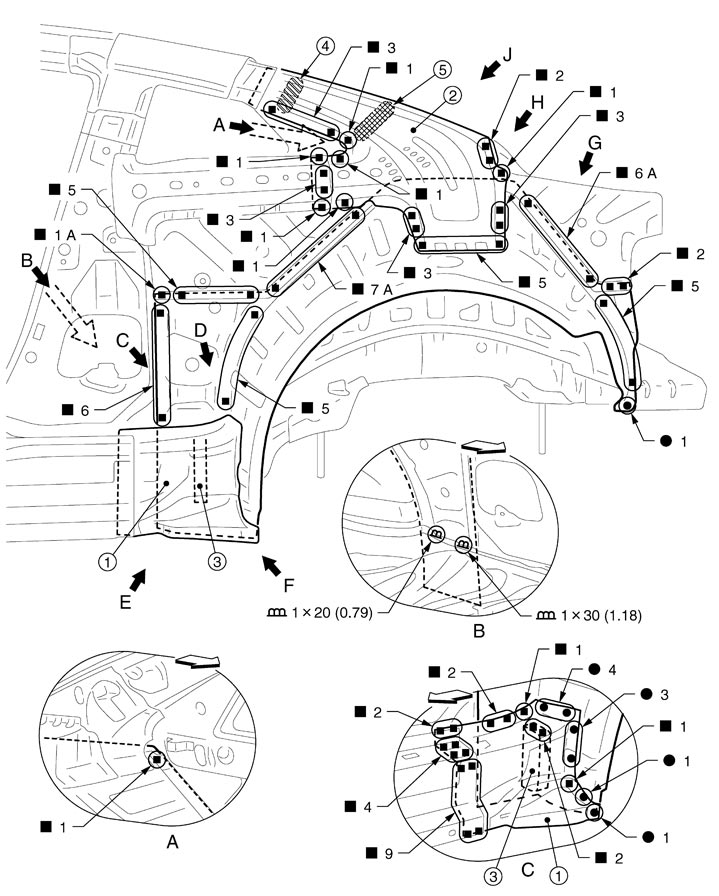
| 1. | Outer sill reinforcement rear | 2. | Rear pillar reinforcement | 3. | Outer rear sill brace |
| 4. | Urethane foam | 5. | Highly rigid foaming agent | ||
| Unit: mm (in) | |||||
| : Vehicle front | ||||
| Replaced parts | |||||
| • | Outer rear wheelhouse (LH) | ||||
■ CAUTION ■
Refer to Foam Repair (section of Example of highly rigid foaming agent repair procedure) for filling procedure of highly rigid foaming agent. 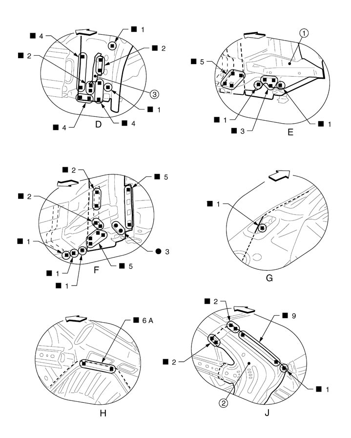
| 1. | Outer sill reinforcement rear | 2. | Rear pillar reinforcement | 3. | Outer rear sill brace |
| Unit: mm (in) | |||||
| : Vehicle front | ||||
View D: Before installing outer sill reinforcement rear
View H: Before installing rear pillar reinforcement
Rear Panel
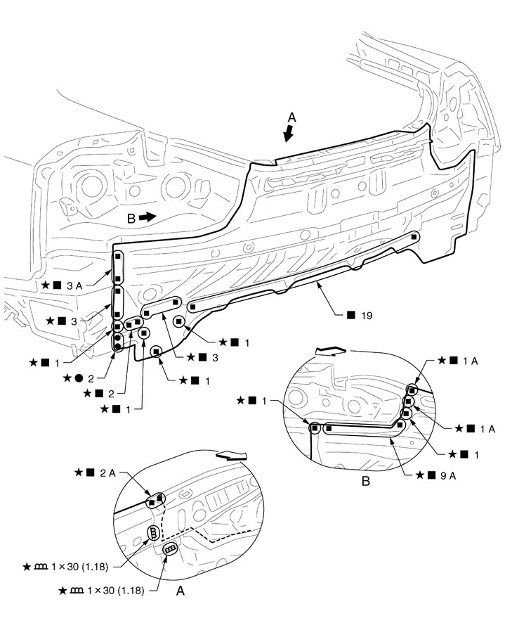
|
Unit: mm (in) |
|
|
|
|
|
|
|
: Vehicle front |
|
|
|
|

|
: An equivalent welding area with the same dimensions is on the opposite side. |
||||
|
Replacement parts |
|||||
|
• |
Rear panel assembly |
|
|
|
|
Rear Floor Rear
Work after rear panel is removed.
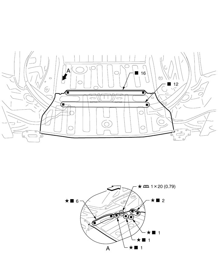
| Unit: mm (in) | |||||
| : Vehicle front | ||||
| : An equivalent welding area with the same dimensions is on the opposite side. | ||||
| Replacement parts | |||||
| • | Rear floor rear | ||||
Rear Side Member
Work after rear fender, rear panel, rear floor rear, rear floor side, lock pillar reinforcement, and outer rear wheelhouse are removed.
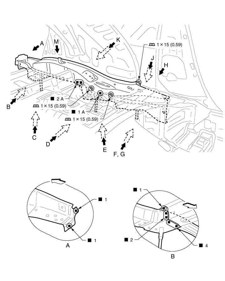
| Unit: mm (in) | |||||
| : Vehicle front | ||||
| Replacement parts | |||||
| • | Rear side member assembly (LH) | ||||
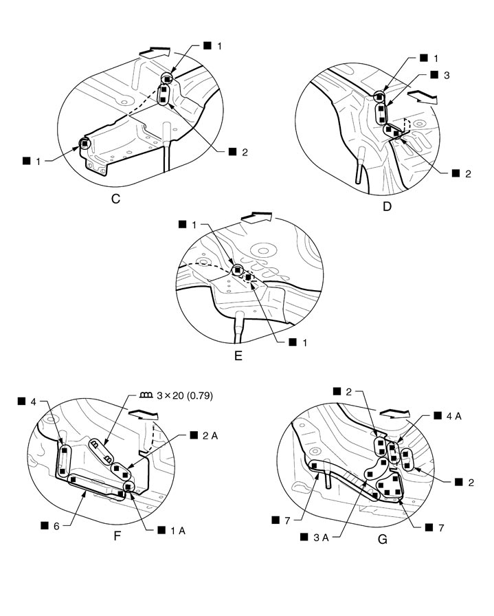
| Unit: mm (in) | |||||
| : Vehicle front | ||||
View G: Before installing jack mounting bracket
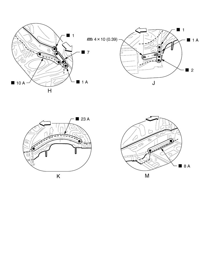
| Unit: mm (in) | |||||
| : Vehicle front | ||||
Rear Side Member Extension
Work after rear panel is removed.
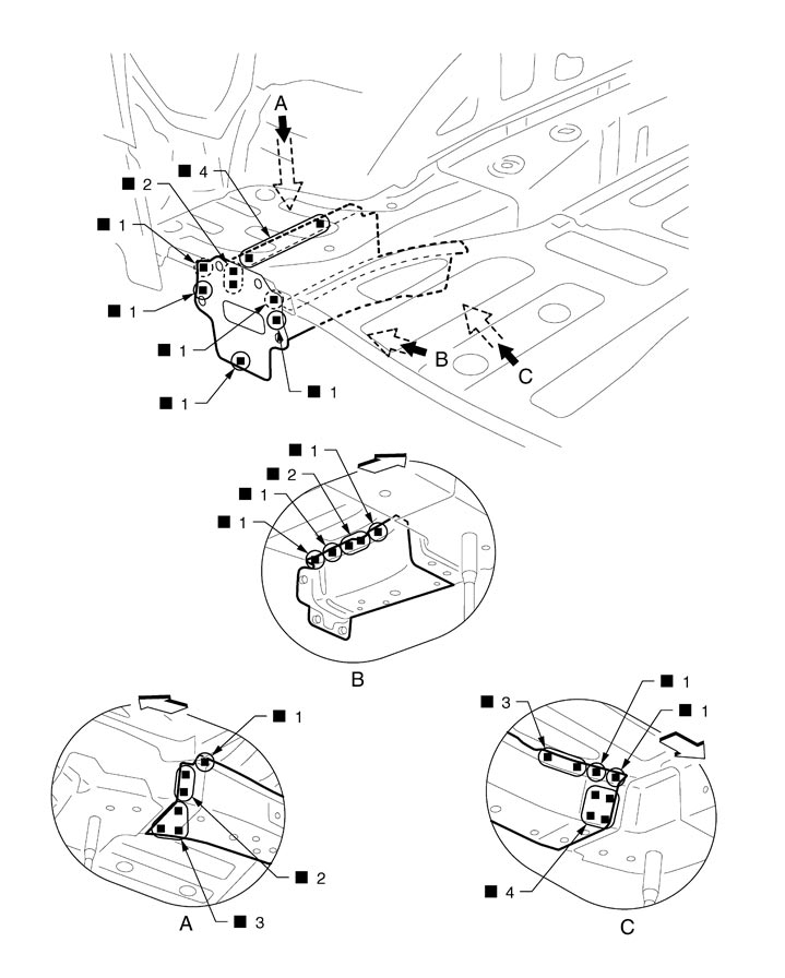
| : Vehicle front | ||||
| Replacement parts | |||||
| • | Rear side member extension (LH) | ||||
Roof
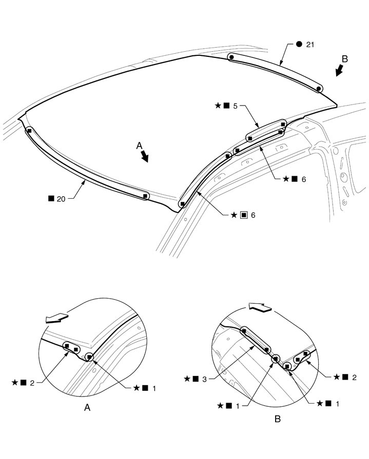
|
|
: Vehicle front |
|
|
|
|
|
|
: An equivalent welding area with the same dimensions is on the opposite side. |
||||
|
Replacement parts |
|
|
|
|
|
|
• |
Roof |
|
|
|
|
Seatback Support
REMOVAL■ CAUTION ■
- Never use an impact wrench to remove or install the mounting bolts and nut.
- Always use the specified bolts and nut with the surface finished.
- Never reuse the removed mounting bolts and nut.
|
|
: Vehicle front |
|
|
|
|
|
|
: Adhesive exfoliated position |
|
|
|
|
|
Refer to ″How to use this manual″Components for the symbols shown in the figure. |
|||||
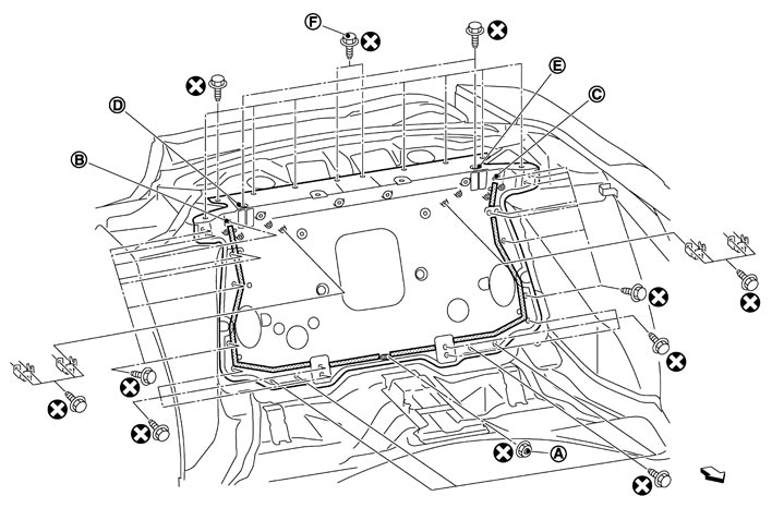
- Remove all of the remaining 30 bolts except the bolts and nut of (A) to (E) shown in the figure. ■ CAUTION ■Tighten 2 bolts (F) together with the parcel shelf reinforcement.
- Loosen the mounting bolts and nut of (A) to (E) to safely unglue the adhesive of seatback support.
- Set the temperature gauge (the infrared noncontact temperature gauge is recommended for temperature management) to the seatback support, and then heat up to 110°C (230°F) using halogen heater, etc. ■ CAUTION ■The heating temperature should not exceed 110°C (230°F).
- Use an L-chisel shaped as shown in the figure and insert it to either the left or right gap between the vehicle body and seatback support on the top of bonding area while heating the seatback support. Slightly unglue the adhesive from the upper side to the lower side to remove the seatback support. ■ CAUTION ■Never damage the seatback support and the portions where the seatback support is bonded.
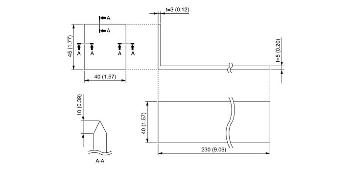
Unit: mm (in) - Eliminate the adhesive that remains on the seatback support and the portions where the seatback support is bonded with a disc sander.
- If the coating on the joint surface with the vehicle is peeled off, apply epoxy primer on the surface to prevent electric corrosion.
INSTALLATION■ CAUTION ■
- Always perform the following procedure to visually check the rear seatback panel for deformation and perform the crack inspection (dye penetrant test) when the vehicle is damaged.
- Spray the cleaning solution on the inspection surface to clean the surface.
- Spray the penetrant liquid on the inspection surface and wait until the liquid is penetrated.
- Wipe out any excess penetrant liquid on the inspection surface and then wipe out again with a cloth moistened by a little cleaning solution.
- Spray the developer on the inspection surface.
- A red indication appears on damaged area.
- Never use an impact wrench to remove or install the mounting bolts and nut.
- Always use the specified bolts and nut with the surface finished.
- Never reuse the removed mounting bolts and nut.
- Tighten all of the mounting bolts and nut before hardening the adhesive.
|
Unit: mm (in) |
|
|
|
|
|
|
|
: 3M™ Automix™ Panel Bonding Adhesive 08115 or equivalent |
|
|
||
|
Refer to ″How to use this manual″Components for the symbols shown in the figure. |
|||||
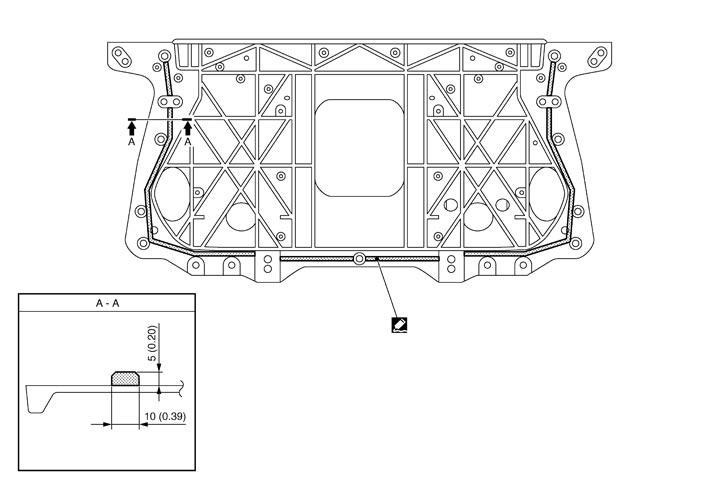
- Apply the adhesive to the seatback support as shown above in the figure.
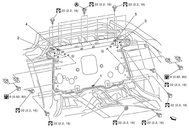
: Vehicle front Refer to ″How to use this manual″Components for the symbols shown in the figure. - Tighten the bolts and nut of 1 to 5 from the mounting bolts and nut in this order to the specified torque in advance. Tighten the remaining bolts evenly in 2 or 3 steps, and then tighten them to the specified torque.
1 : Determine the left or right direction of the center of seatback support bottom in advance, and then tighten to the specified torque. 2, 3 : Determine the top center of the height direction of seatback support in advance, and then tighten to the specified torque. 4, 5 : Determine the left or right direction of the seatback support in advance, and then tighten to the specified torque. ■ CAUTION ■Tighten 2 bolts (A) together with the parcel shelf reinforcement.