DIAGNOSIS SYSTEM (IPDM E/R)
XENON TYPE
Diagnosis Description
 AUTO ACTIVE TEST
 Description
In auto active test mode, the IPDM E/R sends a drive signal to the following systems to check their operation.
- Front wiper (LO, HI)
- Parking lamps
- License plate lamps
- Side marker lamps
- Tail lamps
- Headlamps (LO, HI)
- A/C compressor (magnet clutch)
- Cooling fan (cooling fan control module)
Operation Procedure- 1.Close the hood and lift the wiper arms from the windshield. (Prevent windshield damage due to wiper operation)
NOTE:
When auto active test is performed with hood opened, sprinkle water on windshield beforehand.- 2.Turn the ignition switch OFF.
- 3.Turn the ignition switch ON, and within 20 seconds, press the driver door switch 10 times. Then turn the ignition switch OFF.
■ CAUTION ■
Close passenger door.- 4.Turn the ignition switch ON within 10 seconds. After that the horn sounds once and the auto active test starts.
- 5.After a series of the following operations is repeated 3 times, auto active test is completed.
NOTE:
When auto active test mode has to be cancelled halfway through test, turn the ignition switch OFF.
■ CAUTION ■
- If auto active test mode cannot be actuated, check door switch system. Refer to Component Function Check.
- Do not start the engine.
Inspection in Auto Active Test ModeWhen auto active test mode is actuated, the following 6 steps are repeated 3 times.
| Operation sequence | Inspection location | Operation |
| 1 | Front wiper | LO for 5 seconds → HI for 5 seconds |
| 2 |
| 10 seconds |
| 3 | Headlamps | LO ⇔ HI 5 times |
| 4 | A/C compressor (magnet clutch) | ON ⇔ OFF 5 times |
| 5* | Cooling fan | MID for 5 seconds → HI for 5 seconds |
Concept of auto active test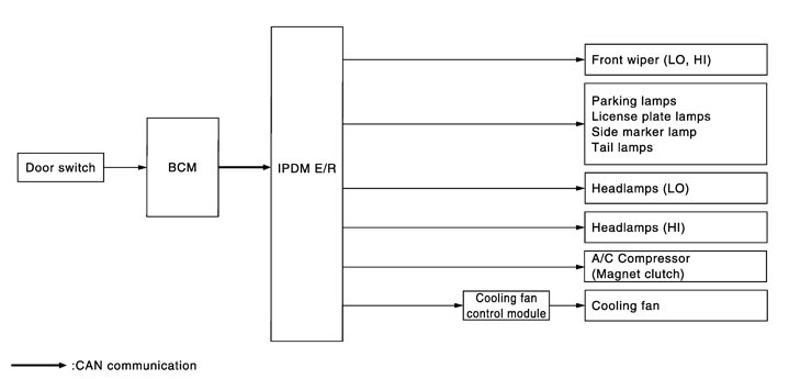
- IPDM E/R starts the auto active test with the door switch signals transmitted by BCM via CAN communication. Therefore, the CAN communication line between IPDM E/R and BCM is considered normal if the auto active test starts successfully.
- The auto active test facilitates troubleshooting if any systems controlled by IPDM E/R cannot be operated.
Diagnosis chart in auto active test mode|
Symptom |
Inspection contents |
Possible cause |
|
|
Any of the following components do not operate
|
Perform auto active test. Does the applicable system operate? |
YES |
BCM signal input circuit |
|
NO |
|
||
|
A/C compressor does not operate |
Perform auto active test. Does the magnet clutch operate? |
YES |
|
|
NO |
|
||
|
Cooling fan does not operate |
Perform auto active test. Does the cooling fan operate? |
YES |
|
|
NO |
|
||
CONSULT-III Function (IPDM E/R)
APPLICATION ITEMCONSULT‐III performs the following functions via CAN communication with IPDM E/R.
| Diagnosis mode | Description |
| Ecu Identification | Allows confirmation of IPDM E/R part number. |
| Self Diagnostic Result | Displays the diagnosis results judged by IPDM E/R. |
| Data Monitor | Displays the real-time input/output data from IPDM E/R input/output data. |
| Active Test | IPDM E/R can provide a drive signal to electronic components to check their operations. |
| CAN Diag Support Monitor | The results of transmit/receive diagnosis of CAN communication can be read. |
SELF DIAGNOSTIC RESULT DATA MONITORMonitor item
| Monitor Item [Unit] | MAIN SIGNALS | Description |
| RAD FAN REQ [%] | × | Displays the value of the cooling fan speed signal received from ECM via CAN communication. |
| AC COMP REQ [Off/On] | × | Displays the status of the A/C compressor request signal received from ECM via CAN communication. |
| TAIL&CLR REQ [Off/On] | × | Displays the status of the position light request signal received from BCM via CAN communication. |
| HL LO REQ [Off/On] | × | Displays the status of the low beam request signal received from BCM via CAN communication. |
| HL HI REQ [Off/On] | × | Displays the status of the high beam request signal received from BCM via CAN communication. |
| FR FOG REQ [Off/On] | × | NOTE: The item is indicated, but not monitored. |
| FR WIP REQ [Stop/1LOW/Low/Hi] | × | Displays the status of the front wiper request signal received from BCM via CAN communication. |
| WIP AUTO STOP [STOP P/ACT P] | × | Displays the status of the front wiper stop position signal judged by IPDM E/R. |
| WIP PROT [Off/BLOCK] | × | Displays the status of the front wiper fail-safe operation judged by IPDM E/R. |
| IGN RLY1 ‐REQ [Off/On] | Displays the status of the ignition switch ON signal received from BCM via CAN communication. | |
| IGN RLY [Off/On] | × | Displays the status of the ignition relay judged by IPDM E/R. |
| PUSH SW [Off/On] | Displays the status of the push‐button ignition switch judged by IPDM E/R. | |
| INTER/NP SW [Off/On] | Displays the status of the shift position judged by IPDM E/R. | |
| ST RLY CONT [Off/On] | Displays the status of the starter relay status signal received from BCM via CAN communication. | |
| IHBT RLY ‐REQ [Off/On] | Displays the status of the starter control relay signal received from BCM via CAN communication. | |
| ST/INHI RLY [Off/ ST /INHI/UNKWN] | Displays the status of the starter relay and starter control relay judged by IPDM E/R. | |
| DETENT SW [Off/On] | Displays the status of the control device (detention switch) judged by IPDM E/R. | |
| S/L RLY ‐REQ [Off/On] | Displays the status of the steering lock relay request signal received from BCM via CAN communication. | |
| S/L STATE [LOCK/UNLOCK/UNKWN] | Displays the status of the steering lock judged by IPDM E/R. | |
| DTRL REQ [Off/On] | × | Displays the status of the daytime running light request signal received from BCM via CAN communication. NOTE: This item is monitored only the vehicle with daytime running light system. |
| OIL P SW [Open/Close] | NOTE: The item is indicated, but not monitored. | |
| HOOD SW [Off/On] | Displays the status of the hood switch judged by IPDM E/R. | |
| HL WASHER REQ [Off] | NOTE: The item is indicated, but not monitored. | |
| THFT HRN REQ [Off/On] | Displays the status of the theft warning horn request signal received from BCM via CAN communication. | |
| HORN CHIRP [Off/On] | Displays the status of the horn reminder signal received from BCM via CAN communication. | |
| CRNRNG LMP REQ [Off] | NOTE: The item is indicated, but not monitored. |
ACTIVE TESTTest item
| Test item | Operation | Description |
| CORNERING LAMP | Off | NOTE: The item is indicated, but cannot be tested. |
| LH | ||
| RH | ||
| HORN | On | Operates horn relay 1 and horn relay 2 for 20 ms. |
| FRONT WIPER | Off | OFF |
| Lo | Operates the front wiper relay. | |
| Hi | Operates the front wiper relay and front wiper high relay. | |
| MOTOR FAN | 1 | OFF |
| 2 | Outputs 50% pulse duty signal (PWM signal) to the cooling fan control module. | |
| 3 | Outputs 80% pulse duty signal (PWM signal) to the cooling fan control module. | |
| 4 | Outputs 100% pulse duty signal (PWM signal) to the cooling fan control module. | |
| HEAD LAMP WASHER | On | NOTE: The item is indicated, but cannot be tested. |
| EXTERNAL LAMPS | Off | OFF |
| TAIL | Operates the tail lamp relay. | |
| Lo | Operates the headlamp low relay. | |
| Hi | Operates the headlamp low relay and ON/OFF the headlamp high relay at 1 second intervals. | |
| Fog | NOTE: The item is indicated, but cannot be tested. |