PRECAUTIONS
CAN
- Precaution for Supplemental Restraint System (SRS) "AIR BAG" and "SEAT BELT PRE-TENSIONER"
- Precaution for Battery Service
- Precautions for Trouble Diagnosis
- Precautions for Harness Repair
Precaution for Supplemental Restraint System (SRS) "AIR BAG" and "SEAT BELT PRE-TENSIONER"
The Supplemental Restraint System such as “AIR BAG” and “SEAT BELT PRE-TENSIONER”, used along with a front seat belt, helps to reduce the risk or severity of injury to the driver and front passenger for certain types of collision. This system includes seat belt switch inputs and dual stage front air bag modules. The SRS system uses the seat belt switches to determine the front air bag deployment, and may only deploy one front air bag, depending on the severity of a collision and whether the front occupants are belted or unbelted.
Information necessary to service the system safely is included in the “SRS AIRBAG” and “SEAT BELT” of this Service Manual.
■ WARNING ■
- To avoid rendering the SRS inoperative, which could increase the risk of personal injury or death in the event of a collision which would result in air bag inflation, all maintenance must be performed by an authorized NISSAN/INFINITI dealer.
- Improper maintenance, including incorrect removal and installation of the SRS, can lead to personal injury caused by unintentional activation of the system. For removal of Spiral Cable and Air Bag Module, see the “SRS AIRBAG”.
- Never use electrical test equipment on any circuit related to the SRS unless instructed to in this Service Manual. SRS wiring harnesses can be identified by yellow and/or orange harnesses or harness connectors.
Precaution for Battery Service
Before disconnecting the battery, lower both the driver and passenger windows. This will prevent any interference between the window edge and the vehicle when the door is opened/closed. During normal operation, the window slightly raises and lowers automatically to prevent any window to vehicle interference. The automatic window function will not work with the battery disconnected.
Precautions for Trouble Diagnosis
■ CAUTION ■
- Never apply 7.0 V or more to the measurement terminal.
- Use a tester with open terminal voltage of 7.0 V or less.
- Turn the ignition switch OFF and disconnect the battery cable from the negative terminal when checking the harness.
Precautions for Harness Repair
- Solder the repaired area and wrap tape around the soldered area.
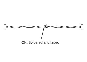 NOTE:A fray of twisted lines must be within 110 mm (4.33 in).
 - Bypass connection is never allowed at the repaired area.
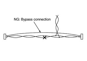 NOTE:Bypass connection may cause CAN communication error. The spliced wire becomes separated and the characteristics of twisted line are lost.
 - Replace the applicable harness as an assembly if error is detected on the shield lines of CAN communication line.