INTAKE SENSOR
AUTOMATIC AIR CONDITIONER
Exploded View
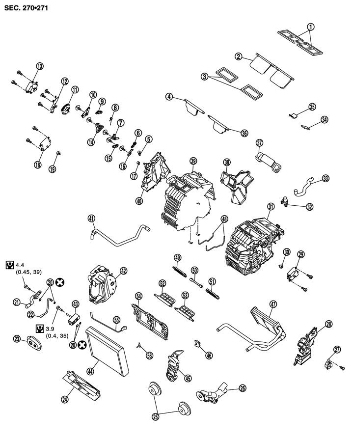
|
1. |
Ventilator seal |
2. |
Ventilator door |
3. |
Defroster seal |
|
4. |
Defroster door (right) |
5. |
Foot door lever |
6. |
Defroster door lever |
|
7. |
Foot door link |
8. |
Ventilator door spring |
9. |
Ventilator door lever |
|
10. |
Ventilator door link |
11. |
Main link |
12. |
Mode door motor bracket |
|
13. |
Mode door motor |
14. |
Main link sub |
15. |
Max. cool door link |
|
16. |
Defroster door link |
17. |
Max. cool door lever |
18. |
Air mix door motor (passenger side) |
|
19. |
Air mix door adapter |
20. |
O‐ring |
21. |
Low‐pressure pipe 1 |
|
22. |
High‐pressure pipe 3 |
23. |
Cooler pipe grommet |
24. |
Insulator |
|
25. |
Heater pipe grommet |
26. |
Heater pipe cover |
27. |
Heater duct |
|
28. |
Foot duct (left) |
29. |
Air mix door motor (driver side) |
30. |
Air mix door adapter |
|
31. |
Heater & cooling unit case (left) |
32. |
Aspirator |
33. |
Aspirator hose |
|
34. |
Packing |
35. |
Packing |
36. |
Defroster door (left) |
|
37. |
Rear ventilator cover |
38. |
Center case |
39. |
Heater & cooling unit case (right) |
|
40. |
Foot duct (right) |
41. |
Drain hose |
42. |
Evaporator cover |
|
43. |
Expansion valve |
44. |
Evaporator |
45. |
Evaporator cover adapter |
|
46. |
Heater pipe bracket |
47. |
Heater core |
48. |
Packing |
|
49. |
Foot door (right) |
50. |
Rear ventilator door |
51. |
Foot door (left) |
|
52. |
Max. cool door (right) |
53. |
Max. cool door (left) |
54. |
Air mix door (Slide door) |
|
55. |
Intake sensor |
56. |
Intake sensor bracket |
|
|
|
Refer to Components for symbols in the figure. |
|||||
Removal and Installation
 REMOVAL
- 1.Remove low‐pressure pipe 1 and high‐pressure pipe 3. Refer to Exploded View (GT-R certified NISSAN dealer).
■ CAUTION ■
Cap or wrap the joint of the cooler piping with suitable material such as vinyl tape to avoid the entry of air.- 2.Disconnect intake sensor connector.
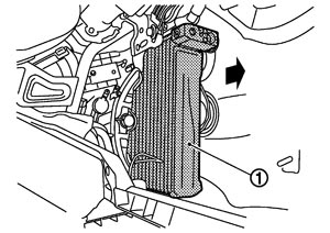
- 3.Slide evaporator (1) to passenger side, and then remove evaporator from heater & cooling unit assembly.
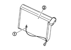
- 4.Remove intake sensor (1) from evapotator (2).
 INSTALLATION
Installation is basically the reverse order of removal.
■ CAUTION ■
- Replace O‐rings with new ones. Then apply compressor oil to them when installing.
- Mark the mounting position of intake sensor bracket prior to removal so that the reinstalled sensor can be located in the same position.
- Female‐side piping connection is thin and easy to deform. Slowly insert the male‐side piping straight in axial direction.
- Insert piping securely until a click is heard.
- After piping connection is completed, pull male‐side piping by hand to make sure that connection does not come loose.
- Check for leakages when recharging refrigerant.