PRECAUTIONS
- Precaution for Supplemental Restraint System (SRS) "AIR BAG" and "SEAT BELT PRE-TENSIONER"
- Aluminum Die-Casting Parts Handling
- Precaution Necessary for Steering Wheel Rotation after Battery Disconnect
- Precaution for Battery Service
- Precaution for Procedure without Cowl Top Cover
- Precautions For Xenon Headlamp Service
Precaution for Supplemental Restraint System (SRS) "AIR BAG" and "SEAT BELT PRE-TENSIONER"
The Supplemental Restraint System such as “AIR BAG” and “SEAT BELT PRE-TENSIONER”, used along with a front seat belt, helps to reduce the risk or severity of injury to the driver and front passenger for certain types of collision. This system includes seat belt switch inputs and dual stage front air bag modules. The SRS system uses the seat belt switches to determine the front air bag deployment, and may only deploy one front air bag, depending on the severity of a collision and whether the front occupants are belted or unbelted.
Information necessary to service the system safely is included in the “SRS AIRBAG” and “SEAT BELT” of this Service Manual.
■ WARNING ■
- To avoid rendering the SRS inoperative, which could increase the risk of personal injury or death in the event of a collision which would result in air bag inflation, all maintenance must be performed by an authorized NISSAN/INFINITI dealer.
- Improper maintenance, including incorrect removal and installation of the SRS, can lead to personal injury caused by unintentional activation of the system. For removal of Spiral Cable and Air Bag Module, see the “SRS AIRBAG”.
- Never use electrical test equipment on any circuit related to the SRS unless instructed to in this Service Manual. SRS wiring harnesses can be identified by yellow and/or orange harnesses or harness connectors.
Aluminum Die-Casting Parts Handling
 PROHIBITION OF WELDING OR BEATING REPAIR
- Material made of aluminum die-casting parts is heat-treated and looses strength when being exposed to welding heat. Do not perform welding repair for cracks, damage or others.
- For aluminum die-casting parts deformation, do not perform repair by beating. Always repair by replacement as an assembly.
CRACK CHECKWhen the vehicle is damaged, always perform a visual deformation check and a crack check.
 Crack Check Procedures
For a crack check, use dye penetrant inspection fluid (pre-cleaning fluid, penetrant fluid and developer fluid).
■ CAUTION ■
Always perform a crack check in accordance with the procedures specified by the manufacturer of the dye penetrant inspection fluid.- 1.Spray pre-cleaning fluid on the checking surface for cleaning.
- 2.Spray penetrant fluid on the checking surface and wait until the penetrant fluid soaks into any cracks.
- 3.Wipe off excessive penetrant fluid, and then also lightly wipe off penetrant fluid using a wet cloth.
- 4.Spray developer fluid on the checking surface.
- 5.Cracks, if any, are dyed red in color.
STRAY CURRENT CORROSION- Corrosion occurs to aluminum die-casting parts by the stray current corrosion phenomenon, when directly contacting other parts made of steel. Always apply anti-stray current corrosion paint (primer) on the mounting surface.
- Clean mounting surface to prevent any foreign matter, steel powder or others from being mixed in. Always apply the specified adhesive when installing.
- Corrosion by stray current corrosion may occur when installing with any other bolts than the specified bolt. Always use the specified bolt that is surface treated.
- When loosening the specified bolt that is tightened, the treated surface may peel. Never reuse the specified bolt that is tightened once.
TIGHTENING TORQUE CONTROLMaterial made of aluminum die-casting parts is soft in term of hardness. Tightening torque must be controlled exactly as specified. Always use a torque wrench to install any part to the specified tightening torque.
■ WARNING ■
Never use a power tool to remove or tighten bolts for aluminum die-casting part.Precaution Necessary for Steering Wheel Rotation after Battery Disconnect
NOTE:
- Before removing and installing any control units, first turn the push-button ignition switch to the LOCK position, then disconnect both battery cables.
- After finishing work, confirm that all control unit connectors are connected properly, then re-connect both battery cables.
- Always use CONSULT-III to perform self-diagnosis as a part of each function inspection after finishing work. If a DTC is detected, perform trouble diagnosis according to self-diagnosis results.
This vehicle is equipped with a push-button ignition switch and a steering lock unit.
If the battery is disconnected or discharged, the steering wheel will lock and cannot be turned.
If turning the steering wheel is required with the battery disconnected or discharged, follow the procedure below before starting the repair operation.
OPERATION PROCEDURE- 1.Connect both battery cables.
NOTE:
Supply power using jumper cables if battery is discharged.- 2.Turn the push-button ignition switch to ACC position.(At this time, the steering lock will be released.)
- 3.Disconnect both battery cables. The steering lock will remain released with both battery cables disconnected and the steering wheel can be turned.
- 4.Perform the necessary repair operation.
- 5.When the repair work is completed, re-connect both battery cables. With the brake pedal released, turn the push-button ignition switch from ACC position to ON position, then to LOCK position. (The steering wheel will lock when the push-button ignition switch is turned to LOCK position.)
- 6.Perform self-diagnosis check of all control units using CONSULT-III.
Precaution for Battery Service
Before disconnecting the battery, lower both the driver and passenger windows. This will prevent any interference between the window edge and the vehicle when the door is opened/closed. During normal operation, the window slightly raises and lowers automatically to prevent any window to vehicle interference. The automatic window function will not work with the battery disconnected.
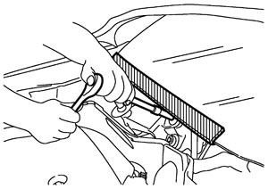
Precaution for Procedure without Cowl Top Cover
When performing the procedure after removing cowl top cover, cover the lower end of windshield with urethane, etc.
Precautions For Xenon Headlamp Service
■ WARNING ■
Comply with the following warnings to prevent any serious accident.- Disconnect the battery cable (negative terminal) or the power supply fuse before installing, removing, or touching the xenon headlamp (bulb included). The xenon headlamp contains high-voltage generated parts.
- Never work with wet hands.
- Check the xenon headlamp ON-OFF status after assembling it to the vehicle. Never turn the xenon headlamp ON in other conditions. Connect the power supply to the vehicle-side connector.
(Turning it ON outside the lamp case may cause fire or visual impairments.) - Never touch the bulb glass immediately after turning it OFF. It is extremely hot.
■ CAUTION ■
Comply with the following cautions to prevent any error and malfunction.- Install the xenon bulb securely. (Insufficient bulb socket installation may melt the bulb, the connector, the housing, etc. by high-voltage leakage or corona discharge.)
- Never perform HID circuit inspection with a tester.
- Never touch the xenon bulb glass with hands. Never put oil and grease on it.
- Dispose of the used xenon bulb after packing it in thick vinyl without breaking it.
- Never wipe out dirt and contamination with organic solvent (thinner, gasoline, etc.).