MULTIPORT FUEL INJECTION SYSTEM
VR38
System Diagram
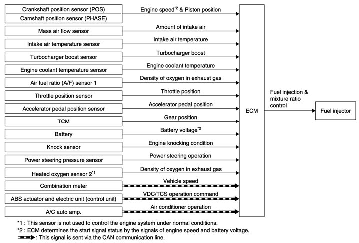
System Description
 INPUT/OUTPUT SIGNAL CHART
|
Sensor |
Input Signal to ECM |
ECM function |
Actuator |
|
Crankshaft position sensor (POS) |
Engine speed*3 Piston position |
Fuel injection & mixture ratio control |
Fuel injector |
|
Camshaft position sensor (PHASE) |
|||
|
Mass air flow sensor |
Amount of intake air |
||
|
Intake air temperature sensor |
Intake air temperature |
||
|
Turbocharger boost sensor |
Turbocharger boost |
||
|
Engine coolant temperature sensor |
Engine coolant temperature |
||
|
Air fuel ratio (A/F) sensor 1 |
Density of oxygen in exhaust gas |
||
|
Throttle position sensor |
Throttle position |
||
|
Accelerator pedal position sensor |
Accelerator pedal position |
||
|
TCM |
Gear position |
||
|
Battery |
Battery voltage*3 |
||
|
Knock sensor |
Engine knocking condition |
||
|
Power steering pressure sensor |
Power steering operation |
||
|
Heated oxygen sensor 2*1 |
Density of oxygen in exhaust gas |
||
|
Combination meter |
Vehicle speed*2 |
||
|
ABS actuator and electric unit (control unit) |
VDC/TCS operation command*2 |
||
|
A/C auto amp |
Air conditioner operation*2 |
SYSTEM DESCRIPTIONThe amount of fuel injected from the fuel injector is determined by the ECM. The ECM controls the length of time the valve remains open (injection pulse duration). The amount of fuel injected is a program value in the ECM memory. The program value is preset by engine operating conditions. These conditions are determined by input signals (for engine speed, intake air and boost) from the crankshaft position sensor (POS), camshaft position sensor (PHASE), mass air flow sensor and the turbocharge boost sensor.
VARIOUS FUEL INJECTION INCREASE/DECREASE COMPENSATIONIn addition, the amount of fuel injected is compensated to improve engine performance under various operating conditions as listed below.
<Fuel increase>
- During warm-up
- When starting the engine
- During acceleration
- Hot-engine operation
- When selector lever is changed from N to D
- High-load, high-speed operation
<Fuel decrease>
- During deceleration
- During high engine speed operation
MIXTURE RATIO FEEDBACK CONTROL (CLOSED LOOP CONTROL)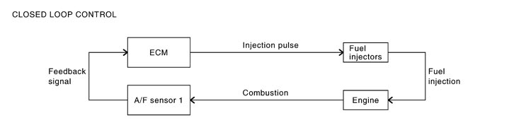
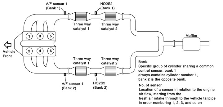
The mixture ratio feedback system provides the best air-fuel mixture ratio for derivatively and emission control. The three way catalyst 1 can better reduce CO, HC and NOx emissions. This system uses A/F sensor 1 in the exhaust manifold to monitor whether the engine operation is rich or lean. The ECM adjusts the injection pulse width according to the sensor voltage signal. For more information about A/F sensor 1, refer to Description (GT-R certified NISSAN dealer). This maintains the mixture ratio within the range of stoichiometric (ideal air-fuel mixture).
This stage is referred to as the closed loop control condition.
Heated oxygen sensor 2 is located downstream of the three way catalyst 1. Even if the switching characteristics of A/F sensor 1 shift, the air-fuel ratio is controlled to stoichiometric by the signal from heated oxygen sensor 2.
- Open Loop ControlThe open loop system condition refers to when the ECM detects any of the following conditions. Feedback control stops in order to maintain stabilized fuel combustion.
- Deceleration and acceleration
- Malfunction of A/F sensor 1 or its circuit
- Insufficient activation of A/F sensor 1 at low engine coolant temperature
- High engine coolant temperature
- During warm-up
- After shifting from N to D
- When starting the engine
MIXTURE RATIO SELF-LEARNING CONTROLThe mixture ratio feedback control system monitors the mixture ratio signal transmitted from A/F sensor 1. This feedback signal is then sent to the ECM. The ECM controls the basic mixture ratio as close to the theoretical mixture ratio as possible. However, the basic mixture ratio is not necessarily controlled as originally designed. Both manufacturing differences (i.e., mass air flow sensor hot wire) and characteristic changes during operation (i.e., fuel injector clogging) directly affect mixture ratio.
Accordingly, the difference between the basic and theoretical mixture ratios is monitored in this system. This is then computed in terms of “injection pulse duration” to automatically compensate for the difference between the two ratios.
“Fuel trim” refers to the feedback compensation value compared against the basic injection duration. Fuel trim includes short term fuel trim and long term fuel trim.
“Short term fuel trim” is the short-term fuel compensation used to maintain the mixture ratio at its theoretical value. The signal from A/F sensor 1 indicates whether the mixture ratio is RICH or LEAN compared to the theoretical value. The signal then triggers a reduction in fuel volume if the mixture ratio is rich, and an increase in fuel volume if it is lean.
“Long term fuel trim” is overall fuel compensation carried out over time to compensate for continual deviation of the short term fuel trim from the central value. Continual deviation will occur due to individual engine differences, wear over time and changes in the usage environment.
FUEL INJECTION TIMING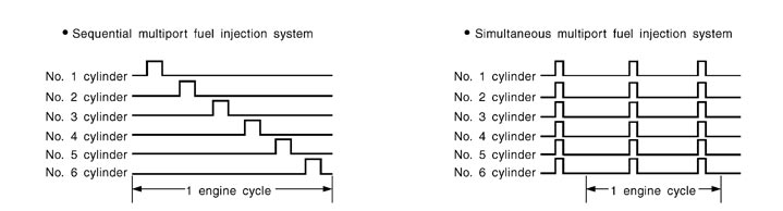
Two types of systems are used.
- Sequential Multiport Fuel Injection SystemFuel is injected into each cylinder during each engine cycle according to the firing order. This system is used when the engine is running.
- Simultaneous Multiport Fuel Injection SystemFuel is injected simultaneously into all six cylinders twice each engine cycle. In other words, pulse signals of the same width are simultaneously transmitted from the ECM.The six injectors will then receive the signals two times for each engine cycle.This system is used when the engine is being started and/or if the fail-safe system (CPU) is operating.
FUEL SHUT-OFFFuel to each cylinder is cut off during deceleration, operation of the engine at excessively high speeds or operation of the vehicle at excessively high speeds.
Component Parts Location
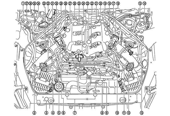
|
1. |
Air cut solenoid valve relay |
2. |
Recirculation valve (bank 1) |
3. |
Refrigerant pressure sensor |
|
4. |
Mass air flow sensor (with intake air temperature sensor) (bank 1) |
5. |
Power steering pressure sensor |
6. |
EVAP canister purge volume control solenoid valve |
|
7. |
Cooling fan motor |
8. |
Cooling fan control module |
9. |
Intake valve timing control solenoid valve |
|
10. |
Turbocharger boost control solenoid valve |
11. |
Mass air flow sensor (with intake air temperature sensor) (bank 2) |
12. |
Recirculation valve (bank 2) |
|
13. |
Turbocharger boost sensor (bank 2) |
14. |
Cooling fan relay-1 |
15. |
Cooling fan relay-2 |
|
16. |
Electric throttle control actuator (bank 2) |
17. |
Ignition coil (with power transistor) and spark plug (bank 2) |
18. |
Camshaft position sensor (PHASE) (bank 2) |
|
19. |
Air cut solenoid valve (bank 2) |
20. |
Crankshaft position sensor (POS) |
21. |
Fuel injector (bank 2) |
|
22. |
Knock sensor |
23. |
Engine oil temperature sensor |
24. |
Fuel injector (bank 1) |
|
25. |
Engine coolant temperature sensor |
26. |
A/F sensor 1 (bank 1) |
27. |
Camshaft position sensor (PHASE) (bank 1) |
|
28. |
Air cut solenoid valve (bank 1) |
29. |
Manifold absolute pressure sensor |
30. |
Ignition coil (with power transistor) and spark plug (bank 1) |
|
31. |
Electric throttle control actuator (bank 1) |
32. |
EVAP service port |
33. |
Turbocharger boost sensor (bank 1) |
|
34. |
IPDM E/R |
35. |
Air pump cleaner |
36. |
Air pump |
|
37. |
Air pump relay |
|
|
|
|
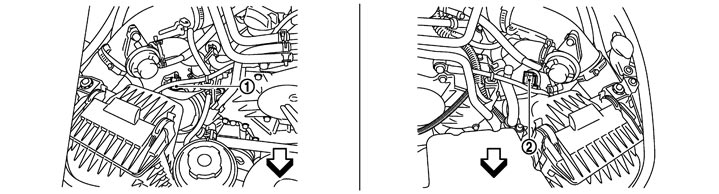
|
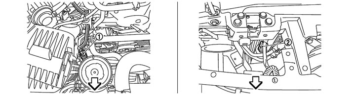
1. |
Mass air flow sensor (with intake air temperature sensor) (bank 1) |
2. |
Mass air flow sensor (with intake air temperature sensor) (bank 2) |
|
|

|
:Vehicle front |
|
|
|
|
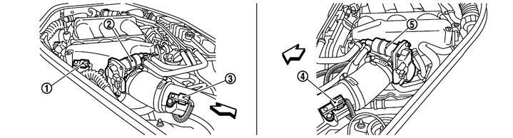
|
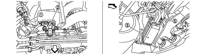
1. |
Manifold absolute pressure sensor |
2. |
Electric throttle control actuator (bank 1) |
3. |
Turbocharger boost sensor (bank 1) |
|
4. |
Turbocharger boost sensor (bank 2) |
5. |
Electric throttle control actuator (bank 2) |
|
|
|
|
:Vehicle front |
|
|
|
|
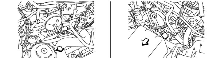
|
1. |
Intake valve timing control solenoid valve (bank1) |
2. |
Intake valve timing control solenoid valve (bank2) |
|
|
|
|
:Vehicle front |
|
|
|
|
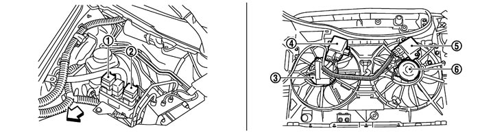
|
1. |
Cooling fan relay-2 |
2. |
Cooling fan relay-1 |
3. |
Cooling fan motor-1 |
|
4. |
Cooling fan control module-1 |
5. |
Cooling fan control module-2 |
6. |
Cooling fan motor-2 |
|
|
:Vehicle front |
|
|
|
|
|
1. |
Power steering pressure sensor |
2. |
Refrigerant pressure sensor |
|
|
|
|
:Vehicle front |
|
|
|
|
|
1. |
EVAP service port |
2. |
EVAP canister purge volume control solenoid valve |
3. |
EVAP canister |
|
4. |
EVAP control system pressure sensor |
5. |
EVAP canister vent control valve |
|
|
|
|
:Vehicle front |
|
|
|
|
|
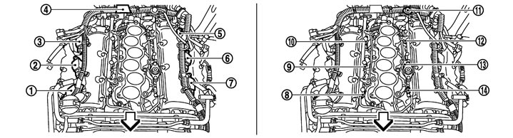
1. |
Ignition coil No.1 (with power transistor) |
2. |
Ignition coil No.3 (with power transistor) |
3. |
Ignition coil No.5 (with power transistor) |
|
4. |
Condenser |
5. |
Ignition coil No.6 (with power transistor) |
6. |
Ignition coil No.4 (with power transistor) |
|
7. |
Ignition coil No.2 (with power transistor) |
8. |
Fuel injector No.1 |
9. |
Fuel injector No.3 |
|
10. |
Fuel injector No.5 |
11. |
Fuel pressure regulator |
12. |
Fuel injector No.6 |
|
13. |
Fuel injector No.4 |
14. |
Fuel injector No.2 |
|
|
|
|
:Vehicle front |
|
|
|
|
|
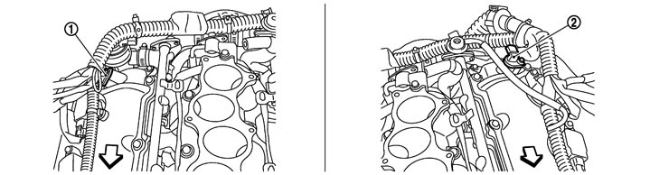
1. |
Camshaft position sensor (PHASE) (bank 1) |
2. |
Camshaft position sensor (PHASE) (bank 2) |
|
|
|
|
:Vehicle front |
|
|
|
|
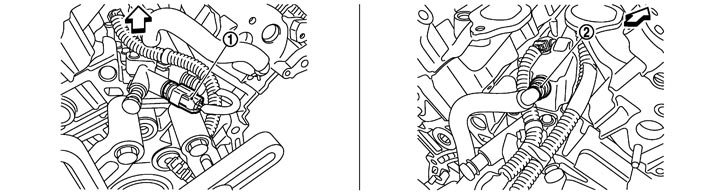
|
1. |
Engine oil temperature sensor |
2. |
PCV valve |
|
|
|
|
:Vehicle front |
|
|
|
|
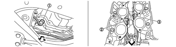
|
1. |
Crankshaft position sensor (POS) |
2. |
Knock sensor (bank1) |
3. |
Knock sensor (bank2) |
|
|
:Vehicle front |
|
|
|
|
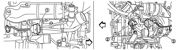
|
1. |
Boost control actuator (bank1) |
2. |
Turbocharger boost control solenoid valve |
3. |
Boost control actuator (bank2) |
|
|
:Vehicle front |
|
|
|
|
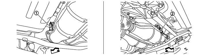
|
1. |
Heated oxygen sensor 2 (bank 2) |
2. |
Heated oxygen sensor 2 (bank 1) |
|
|
|
|
:Vehicle front |
|
|
|
|
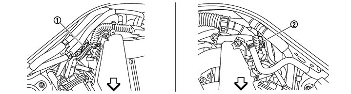
|
1. |
A/F sensor 1 (bank 1) harness connector |
2. |
A/F sensor 1 (bank 2) harness connector |
|
|
|
|
:Vehicle front |
|
|
|
|
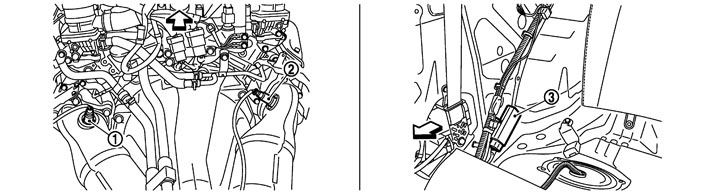
|
1. |
A/F sensor 1 (bank 2) |
2. |
A/F sensor 1 (bank 1) |
3. |
Fuel pump control module (FPCM) |
|
|
:Vehicle front |
|
|
|
|
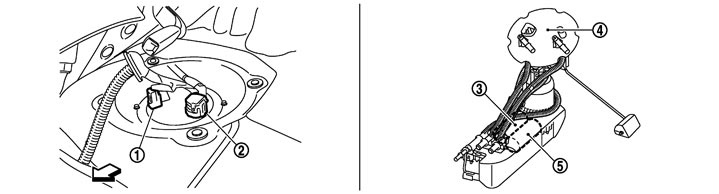
|
1. |
Sub fuel pump harness connector |
2. |
Main fuel gauge fuel filter fuel pump assembly harness connector |
3. |
Sub fuel pump |
|
4. |
Main fuel gauge fuel filter fuel pump assembly |
5. |
Fuel pump |
|
|
|
|
:Vehicle front |
|
|
|
|
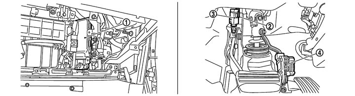
|
1. |
ECM |
2. |
Brake switch |
3. |
Stop lamp switch |
|
4. |
Accelerator pedal position sensor |
|
|
|
|
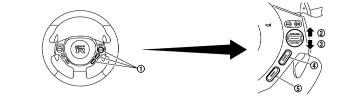
|
1. |
ASCD steering switch |
2. |
RESUME/ACCELERATE switch |
3. |
SET/COAST switch |
|
4. |
CANCEL switch |
5. |
MAIN switch |
|
|
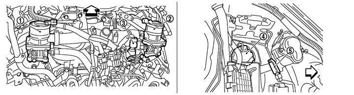
|
1. |
Air cut solenoid valve (bank 2) |
2. |
Air cut solenoid valve (bank 1) |
3. |
Engine coolant temperature sensor |
|
4. |
Air pump |
5. |
Secondary air injection system mass air flow sensor |
|
|
|
|
:Vehicle front |
|
|
|
|

|
1. |
Air cut solenoid valve relay |
2. |
Air pump relay |
3. |
Air pump cleaner |
|
4. |
IPDM E/R |
|
|
|
|
Component Description
|
Component |
Reference |
|
A/F sensor 1 |
Description (GT-R certified NISSAN dealer)
|
|
Accelerator pedal position sensor |
Description (GT-R certified NISSAN dealer)
|
|
Camshaft position sensor (PHASE) |
Description (GT-R certified NISSAN dealer)
|
|
Crankshaft position sensor (POS) |
Description (GT-R certified NISSAN dealer)
|
|
Engine coolant temperature sensor |
Description (GT-R certified NISSAN dealer)
|
|
Fuel injector |
Description (GT-R certified NISSAN dealer)
|
|
Heated oxygen sensor 2 |
Description (GT-R certified NISSAN dealer)
|
|
Intake air temperature sensor |
Description (GT-R certified NISSAN dealer)
|
|
Knock sensor |
Description (GT-R certified NISSAN dealer)
|
|
Mass air flow sensor |
Description (GT-R certified NISSAN dealer)
|
|
Power steering pressure sensor |
Description (GT-R certified NISSAN dealer)
|
|
Throttle position sensor |
Description (GT-R certified NISSAN dealer)
|
|
Turbocharger boost sensor |
Description (GT-R certified NISSAN dealer)
|