BCM (BODY CONTROL MODULE)
- Reference Value
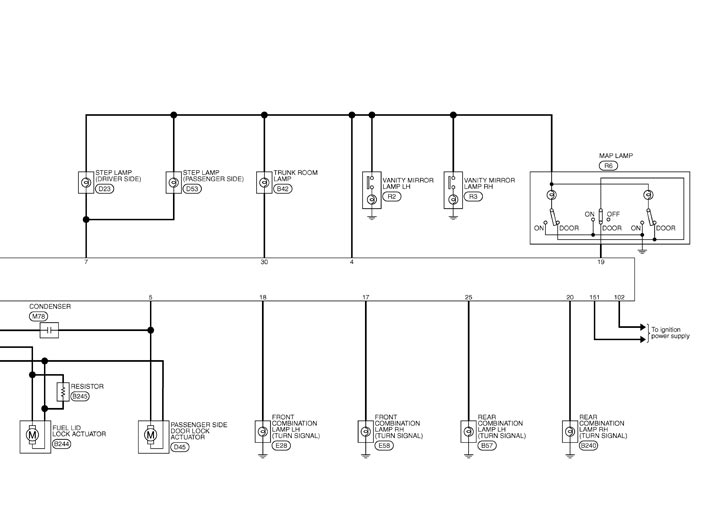
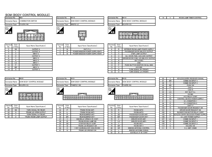
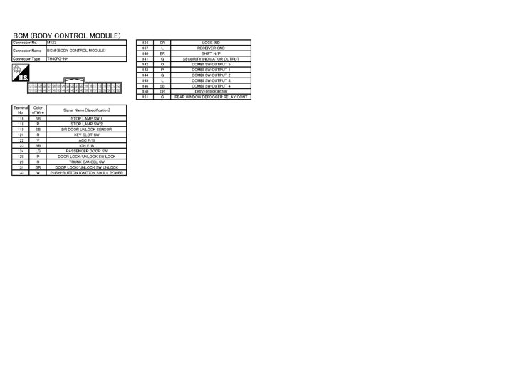
- Wiring Diagram - BCM -
- Fail-safe
- DTC Inspection Priority Chart
- DTC Index
Reference Value
 VALUES ON THE DIAGNOSIS TOOL
CONSULT-III MONITOR ITEM
|
Monitor Item |
Condition |
Value/Status | |
| FR WIPER HI | Other than front wiper switch HI | Off | |
| Front wiper switch HI | On | ||
| FR WIPER LOW | Other than front wiper switch LO | Off | |
| Front wiper switch LO | On | ||
| FR WASHER SW | Front washer switch OFF | Off | |
| Front washer switch ON | On | ||
| FR WIPER INT | Other than front wiper switch INT | Off | |
| Front wiper switch INT | On | ||
| FR WIPER STOP | Front wiper is not in STOP position | Off | |
| Front wiper is in STOP position | On | ||
| INT VOLUME | Wiper intermittent dial is in a dial position 1 ‐ 7 | Wiper intermittent dial position | |
| TURN SIGNAL R | Other than turn signal switch RH | Off | |
| Turn signal switch RH | On | ||
| TURN SIGNAL L | Other than turn signal switch LH | Off | |
| Turn signal switch LH | On | ||
| TAIL LAMP SW | Other than lighting switch 1ST and 2ND | Off | |
| Lighting switch 1ST or 2ND | On | ||
| HI BEAM SW | Other than lighting switch HI | Off | |
| Lighting switch HI | On | ||
| HEAD LAMP SW 1 | Other than lighting switch 2ND | Off | |
| Lighting switch 2ND | On | ||
| HEAD LAMP SW 2 | Other than lighting switch 2ND | Off | |
| Lighting switch 2ND | On | ||
| PASSING SW | Other than lighting switch PASS | Off | |
| Lighting switch PASS | On | ||
| FR FOG SW | NOTE: The item is indicated, but not monitored. | Off | |
| RR FOG SW | NOTE: The item is indicated, but not monitored. | Off | |
| DOOR SW-DR | Driver door closed | Off | |
| Driver door opened | On | ||
| DOOR SW-AS | Passenger door closed | Off | |
| Passenger door opened | On | ||
| DOOR SW-RR | NOTE: The item is indicated, but not monitored. | Off | |
| DOOR SW-RL | NOTE: The item is indicated, but not monitored. | Off | |
| DOOR SW-BK | NOTE: The item is indicated, but not monitored. | Off | |
| CDL LOCK SW | Other than power door lock switch LOCK | Off | |
| Power door lock switch LOCK | On | ||
| CDL UNLOCK SW | Other than power door lock switch UNLOCK | Off | |
| Power door lock switch UNLOCK | On | ||
| KEY CYL LK-SW | NOTE: The item is indicated, but not monitored. | Off | |
| KEY CYL UN-SW | NOTE: The item is indicated, but not monitored. | Off | |
| KEY CYL SW-TR | NOTE: The item is indicated, but not monitored. | Off | |
| HAZARD SW | Hazard switch is not pressed | Off | |
| Hazard switch is pressed | On | ||
| REAR DEF SW | NOTE: The item is indicated, but not monitored. | Off | |
| H/L WASH SW | NOTE: The item is indicated, but not monitored. | Off | |
| TR CANCEL SW | Trunk lid opener cancel switch OFF | Off | |
| Trunk lid opener cancel switch ON | On | ||
| TR/BD OPEN SW | Trunk lid opener switch OFF | Off | |
| While the trunk lid opener switch is turned ON | On | ||
| TRNK/HAT MNTR | Trunk lid closed | Off | |
| Trunk lid opened | On | ||
| RKE-LOCK | LOCK button of Intelligent Key is not pressed | Off | |
| LOCK button of Intelligent Key is pressed | On | ||
| RKE-UNLOCK | UNLOCK button of Intelligent Key is not pressed | Off | |
| UNLOCK button of Intelligent Key is pressed | On | ||
| RKE-TR/BD | TRUNK OPEN button of Intelligent Key is not pressed | Off | |
| TRUNK OPEN button of Intelligent Key is pressed | On | ||
| RKE-PANIC | PANIC button of Intelligent Key is not pressed | Off | |
| PANIC button of Intelligent Key is pressed | On | ||
| RKE-P/W OPEN | UNLOCK button of Intelligent Key is not pressed | Off | |
| UNLOCK button of Intelligent Key is pressed and held | On | ||
| RKE-MODE CHG | LOCK/UNLOCK button of Intelligent Key is not pressed and held simultaneously | Off | |
| LOCK/UNLOCK button of Intelligent Key is pressed and held simultaneously | On | ||
| REQ SW-DR | Driver door request switch is not pressed | Off | |
| Driver door request switch is pressed | On | ||
| REQ SW-AS | Passenger door request switch is not pressed | Off | |
| Passenger door request switch is pressed | On | ||
| REQ SW-RL | NOTE: The item is indicated, but not monitored. | Off | |
| REQ SW-RR | NOTE: The item is indicated, but not monitored. | Off | |
| REQ SW-BD/TR | Trunk lid opener request switch is not pressed | Off | |
| Trunk lid opener request switch is pressed | On | ||
| PUSH SW | Push-button ignition switch (push switch) is not pressed | Off | |
| Push-button ignition switch (push switch) is pressed | On | ||
| IGN RLY2 -F/B | Ignition switch in OFF or ACC position | Off | |
| Ignition switch in ON position | On | ||
| ACC RLY -F/B | NOTE: The item is indicated, but not monitored. | Off | |
| CLUCH SW | NOTE: The item is indicated, but not monitored. | Off | |
| BRAKE SW 1 | Stop lamp switch 1 signal circuit is open | Off | |
| Stop lamp switch 1 signal circuit is normal | On | ||
| DETE/CANCL SW | Selector lever in P position | Off | |
| Selector lever in any position other than P | On | ||
| SFT PN/N SW | Selector lever in any position other than P and N | Off | |
| Selector lever in P or N position | On | ||
| S/L -LOCK | Steering is unlocked | Off | |
| Steering is locked | On | ||
| S/L -UNLOCK | Steering is locked | Off | |
| Steering is unlocked | On | ||
| S/L RELAY-F/B | Ignition switch in OFF or ACC position | Off | |
| Ignition switch in ON position | On | ||
| UNLK SEN-DR | Driver door is unlocked | Off | |
| Driver door is locked | On | ||
| PUSH SW -IPDM | Push-button ignition switch (push-switch) is not pressed | Off | |
| Push-button ignition switch (push-switch) is pressed | On | ||
| IGN RLY1 -F/B | Ignition switch in OFF or ACC position | Off | |
| Ignition switch in ON position | On | ||
| DETE SW -IPDM | Selector lever in any position other than P | Off | |
| Selector lever in P position | On | ||
| SFT PN -IPDM | Selector lever in any position other than P and N | Off | |
| Selector lever in P or N position | On | ||
| SFT P -MET | Selector lever in any position other than P | Off | |
| Selector lever in P position | On | ||
| SFT N -MET | Selector lever in any position other than N | Off | |
| Selector lever in N position | On | ||
| ENGINE STATE | Engine stopped | Stop | |
| While the engine stalls | Stall | ||
| At engine cranking | Crank | ||
| Engine running | Run | ||
| S/L LOCK-IPDM | Steering is unlocked | Off | |
| Steering is locked | On | ||
| S/L UNLK-IPDM | Steering is locked | Off | |
| Steering is unlocked | On | ||
| S/L RELAY-REQ | Steering lock system is not the LOCK condition and the changing condition from LOCK to UNLOCK | Off | |
| Steering lock system is the LOCK condition or the changing condition from LOCK to UNLOCK | On | ||
| VEH SPEED 1 | While driving | Equivalent to speedometer reading | |
| VEH SPEED 2 | While driving | Equivalent to speedometer reading | |
| DOOR STAT-DR | Driver door is locked | LOCK | |
| Wait with selective UNLOCK operation (5 seconds) | READY | ||
| Driver door is unlocked | UNLOCK | ||
| DOOR STAT-AS | Passenger door is locked | LOCK | |
| Wait with selective UNLOCK operation (5 seconds) | READY | ||
| Passenger door is unlocked | UNLOCK | ||
| ID OK FLAG | Steering is locked | Reset | |
| Steering is unlocked | Set | ||
| PRMT ENG STRT | The engine start is prohibited | Reset | |
| The engine start is permitted | Set | ||
| PRMT RKE STRT | NOTE: The item is indicated, but not monitored. | Reset | |
| KEY SW -SLOT | Intelligent Key is not inserted into key slot | Off | |
| Intelligent Key is inserted into key slot | On | ||
| RKE OPE COUN1 | During the operation of Intelligent Key | Operation frequency of Intelligent Key | |
| RKE OPE COUN2 | NOTE: The item is indicated, but not monitored. | — | |
| CONFRM ID ALL | The key ID that the key slot receives is not recognized by any key ID registered to BCM. | Yet | |
| The key ID that the key slot receives is recognized by any key ID registered to BCM. | Done | ||
| CONFIRM ID4 | The key ID that the key slot receives is not recognized by the fourth key ID registered to BCM. | Yet | |
| The key ID that the key slot receives is recognized by the fourth key ID registered to BCM. | Done | ||
| CONFIRM ID3 | The key ID that the key slot receives is not recognized by the third key ID registered to BCM. | Yet | |
| The key ID that the key slot receives is recognized by the third key ID registered to BCM. | Done | ||
| CONFIRM ID2 | The key ID that the key slot receives is not recognized by the second key ID registered to BCM. | Yet | |
| The key ID that the key slot receives is recognized by the second key ID registered to BCM. | Done | ||
| CONFIRM ID1 | The key ID that the key slot receives is not recognized by the first key ID registered to BCM. | Yet | |
| The key ID that the key slot receives is recognized by the first key ID registered to BCM. | Done | ||
| TP 4 | The ID of fourth Intelligent Key is not registered to BCM | Yet | |
| The ID of fourth Intelligent Key is registered to BCM | Done | ||
| TP 3 | The ID of third Intelligent Key is not registered to BCM | Yet | |
| The ID of third Intelligent Key is registered to BCM | Done | ||
| TP 2 | The ID of second Intelligent Key is not registered to BCM | Yet | |
| The ID of second Intelligent Key is registered to BCM | Done | ||
| TP 1 | The ID of first Intelligent Key is not registered to BCM | Yet | |
| The ID of first Intelligent Key is registered to BCM | Done | ||
TERMINAL LAYOUT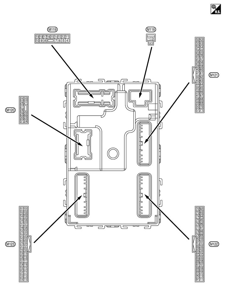 PHYSICAL VALUES
|
Terminal No. (Wire color) |
Description |
Condition |
Value (Approx.) |
|||
|
Signal name |
Input/ Output |
|||||
|
+ |
– |
|||||
|
1 (W) |
Ground |
Battery power supply |
Input |
Ignition switch OFF |
Battery voltage |
|
|
2 (R) |
Ground |
P/W power supply (BAT) |
Output |
Ignition switch OFF |
Battery voltage |
|
|
3 (W) |
Ground |
P/W power supply (RAP) |
Output |
Ignition switch ON |
Battery voltage |
|
|
4 (R) |
Ground |
Interior room lamp power supply |
Output |
After passing the interior room lamp battery saver operation time |
0 V |
|
|
Any other time after passing the interior room lamp battery saver operation time |
Battery voltage |
|||||
|
5 (G) |
Ground |
Passenger door UNLOCK |
Output |
Passenger door |
UNLOCK (Actuator is activated) |
Battery voltage |
|
Other than UNLOCK (Actuator is not activated) |
0 V |
|||||
|
7 (Y) |
Ground |
Step lamp |
Output |
Step lamp |
ON |
0 V |
|
OFF |
Battery voltage |
|||||
|
8 (V) |
Ground |
All doors, fuel lid LOCK |
Output |
All doors, fuel lid |
LOCK (Actuator is activated) |
Battery voltage |
|
Other than LOCK (Actuator is not activated) |
0 V |
|||||
|
9 (G) |
Ground |
Driver door, fuel lid UNLOCK |
Output |
Driver door, fuel lid |
UNLOCK (Actuator is activated) |
Battery voltage |
|
Other than UNLOCK (Actuator is not activated) |
0 V |
|||||
|
11 (R) |
Ground |
Battery power supply |
Input |
Ignition switch OFF |
Battery voltage |
|
|
13 (B) |
Ground |
Ground |
— |
Ignition switch ON |
0 V |
|
|
14 (P) |
Ground |
Push-button ignition switch illumination ground |
Output |
Tail lamp |
OFF |
0 V |
|
ON |
NOTE:
When the illumination brightening/dimming level is in the neutral position
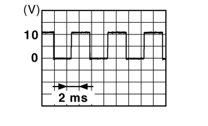
|
|||||
|
15 (Y) |
Ground |
ACC indicator lamp |
Output |
Ignition switch |
OFF (LOCK indicator is not illuminated) |
Battery voltage |
|
ACC or ON |
0 V |
|||||
|
17 (W) |
Ground |
Turn signal RH (Front) |
Output |
Ignition switch ON |
Turn signal switch OFF |
0 V |
|
Turn signal switch RH |
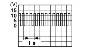
6.5 V |
|||||
|
18 (O) |
Ground |
Turn signal LH (Front) |
Output |
Ignition switch ON |
Turn signal switch OFF |
0 V |
|
Turn signal switch LH |
6.5 V |
|||||
|
19 (V) |
Ground |
Room lamp timer control |
Output |
Interior room lamp |
OFF |
Battery voltage |
|
ON |
0 V |
|||||
|
20 (SB) |
Ground |
Turn signal RH (Rear) |
Output |
Ignition switch ON |
Turn signal switch OFF |
0 V |
|
Turn signal switch RH |
6.5 V |
|||||
|
23 (G) |
Ground |
Trunk lid opening |
Output |
Trunk lid |
Open (Trunk lid opener actuator is activated) |
Battery voltage |
|
Close (Trunk lid opener actuator is not activated) |
0 V |
|||||
|
25 (V) |
Ground |
Turn signal LH (Rear) |
Output |
Ignition switch ON |
Turn signal switch OFF |
0 V |
|
Turn signal switch LH |
6.5 V |
|||||
|
30 (O) |
Ground |
Trunk room lamp |
Output |
Trunk room lamp |
ON |
0 V |
|
OFF |
Battery voltage |
|||||
|
34 (P) |
Ground |
Trunk room antenna (-) |
Output |
Ignition switch OFF |
When Intelligent Key is in the passenger compartment |
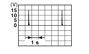
|
|
When Intelligent Key is not in the passenger compartment |
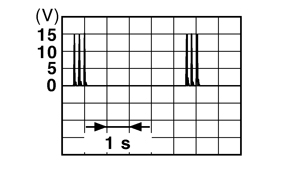
|
|||||
|
35 (L) |
Ground |
Trunk room antenna (+) |
Output |
Ignition switch OFF |
When Intelligent Key is in the passenger compartment |
|
|
When Intelligent Key is not in the passenger compartment |
|
|||||
|
38 (R) |
Ground |
Rear bumper antenna (-) |
Output |
When the trunk lid request switch is operated with ignition switch OFF |
When Intelligent Key is in the antenna detection area |
|
|
When Intelligent Key is not in the antenna detection area |
|
|||||
|
39 (BR) |
Ground |
Rear bumper antenna (+) |
Output |
When the trunk lid request switch is operated with ignition switch OFF |
When Intelligent Key is in the antenna detection area |
|
|
When Intelligent Key is not in the antenna detection area |
|
|||||
|
47 (Y) |
Ground |
Ignition relay (IPDM E/R) control |
Output |
Ignition switch |
OFF or ACC |
Battery voltage |
|
ON |
0 V |
|||||
|
50 (R) |
Ground |
Trunk room lamp switch |
Input |
Trunk room lamp switch |
OFF (Trunk is closed) |
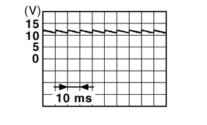
11.8 V |
|
ON (Trunk is open) |
0 V |
|||||
|
52 (SB) |
Ground |
Starter relay control |
Output |
Ignition switch ON |
When selector lever is in P or N position and the brake is depressed |
Battery voltage |
|
When selector lever is in P or N position and the brake is not depressed |
0 V |
|||||
|
61 (W) |
Ground |
Trunk lid request switch |
Input |
Trunk lid request switch |
ON (Pressed) |
0 V |
|
OFF (Not pressed) |
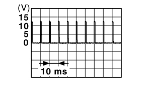
1.0 V |
|||||
|
64 (O) |
Ground |
Intelligent Key warning buzzer (Engine room) |
Output |
Intelligent Key warning buzzer (Engine room) |
Sounding |
0 V |
|
Not sounding |
Battery voltage |
|||||
|
67 (G) |
Ground |
Trunk lid opener switch |
Input |
Trunk lid opener switch |
Pressed |
0 V |
|
Not pressed |
11.8 V |
|||||
|
72 (R) |
Ground |
Room antenna 2 (-) (Center console) |
Output |
Ignition switch OFF |
When Intelligent Key is in the passenger compartment |
|
|
When Intelligent Key is not in the passenger compartment |
|
|||||
|
73 (G) |
Ground |
Room antenna 2 (+) (Center console) |
Output |
Ignition switch OFF |
When Intelligent Key is in the passenger compartment |
|
|
When Intelligent Key is not in the passenger compartment |
|
|||||
|
74 (SB) |
Ground |
Passenger door antenna (-) |
Output |
When the passenger door request switch is operated with ignition switch OFF |
When Intelligent Key is in the antenna detection area |
|
|
When Intelligent Key is not in the antenna detection area |
|
|||||
|
75 (BR) |
Ground |
Passenger door antenna (+) |
Output |
When the passenger door request switch is operated with ignition switch OFF |
When Intelligent Key is in the antenna detection area |
|
|
When Intelligent Key is not in the antenna detection area |
|
|||||
|
76 (V) |
Ground |
Driver door antenna (-) |
Output |
When the driver door request switch is operated with ignition switch OFF |
When Intelligent Key is in the antenna detection area |
|
|
When Intelligent Key is not in the antenna detection area |
|
|||||
|
77 (LG) |
Ground |
Driver door antenna (+) |
Output |
When the driver door request switch is operated with ignition switch OFF |
When Intelligent Key is in the antenna detection area |
|
|
When Intelligent Key is not in the antenna detection area |
|
|||||
|
78 (Y) |
Ground |
Room antenna 1 (-) (Instrument panel) |
Output |
Ignition switch OFF |
When Intelligent Key is in the passenger compartment |
|
|
When Intelligent Key is not in the passenger compartment |
|
|||||
|
79 (BR) |
Ground |
Room antenna 1 (+) (Instrument panel) |
Output |
Ignition switch OFF |
When Intelligent Key is in the passenger compartment |
|
|
When Intelligent Key is not in the passenger compartment |
|
|||||
|
80 (GR) |
Ground |
NATS antenna amp (built in key slot) |
Input/Output |
During waiting |
Ignition switch is pressed while inserting the Intelligent Key into the key slot. |
Just after pressing ignition switch. Pointer of tester should move. |
|
81 (L) |
Ground |
NATS antenna amp (built in key slot) |
Input/Output |
During waiting |
Ignition switch is pressed while inserting the Intelligent Key into the key slot. |
Just after pressing ignition switch. Pointer of tester should move. |
|
82 (R) |
Ground |
Ignition relay [fuse block (J/B)] control |
Output |
Ignition switch |
OFF or ACC |
0 V |
|
ON |
Battery voltage |
|||||
|
83 (Y) |
Ground |
Remote keyless entry receiver |
Input/Output |
During waiting |
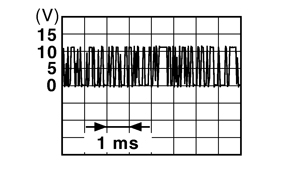
|
|
|
When operating either button on Intelligent Key |
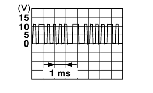
|
|||||
|
87 (BR) |
Ground |
Combination switch INPUT 5 |
Input |
Combination switch |
All switches OFF (Wiper intermittent dial 4) |
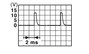
1.4 V |
Any of the conditions below with all switches OFF
|
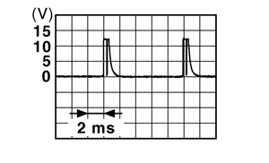
1.3 V |
|||||
|
88 (V) |
Ground |
Combination switch INPUT 3 |
Input |
Combination switch |
All switches OFF (Wiper intermittent dial 4) |
1.4 V |
|
Lighting switch HI (Wiper intermittent dial 4) |
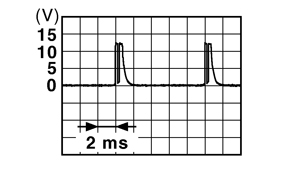
1.3 V |
|||||
|
Lighting switch 2ND (Wiper intermittent dial 4) |
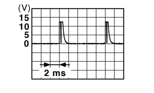
1.3 V |
|||||
Any of the conditions below with all switches OFF
|
1.3 V |
|||||
|
89 (BR) |
Ground |
Push-button ignition switch (push switch) |
Input |
Push-button ignition switch (push switch) |
Pressed |
0 V |
|
Not pressed |
Battery voltage |
|||||
|
90 (P) |
Ground |
CAN ‐ L |
Input/ Output |
— |
— |
|
|
91 (L) |
Ground |
CAN ‐ H |
Input/ Output |
— |
— |
|
|
92 (LG) |
Ground |
Key slot illumination |
Output |
Key slot illumination |
OFF |
0 V |
|
Blinking |
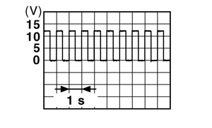
6.5 V |
|||||
|
ON |
Battery voltage |
|||||
|
93 (V) |
Ground |
ON indicator lamp |
Output |
Ignition switch |
OFF (LOCK indicator is not illuminated) |
Battery voltage |
|
ON or ACC |
0 V |
|||||
|
95 (O) |
Ground |
ACC relay control |
Output |
Ignition switch |
OFF |
0 V |
|
ACC or ON |
Battery voltage |
|||||
|
96 (SB) |
Ground |
A/T device (detention switch) power supply |
Output |
— |
Battery voltage |
|
|
97 (L) |
Ground |
Steering lock condition No. 1 |
Input |
Steering lock |
LOCK status |
0 V |
|
UNLOCK status |
Battery voltage |
|||||
|
98 (R) |
Ground |
Steering lock condition No. 2 |
Input |
Steering lock |
LOCK status |
Battery voltage |
|
UNLOCK status |
0 V |
|||||
|
99 (G) |
Ground |
Selector lever P position switch |
Input |
Selector lever |
P position |
0 V |
|
Any position other than P |
Battery voltage |
|||||
|
100 (W) |
Ground |
Passenger door request switch |
Input |
Passenger door request switch |
ON (Pressed) |
0 V |
|
OFF (Not pressed) |
1.0 V |
|||||
|
101 (V) |
Ground |
Driver door request switch |
Input |
Driver door request switch |
ON (Pressed) |
0 V |
|
OFF (Not pressed) |
1.0 V |
|||||
|
102 (O) |
Ground |
Blower fan motor relay control |
Output |
Ignition switch |
OFF or ACC |
0 V |
|
ON |
Battery voltage |
|||||
|
103 (LG) |
Ground |
Remote keyless entry receiver power supply |
Output |
Ignition switch OFF |
Battery voltage |
|
|
106 (P) |
Ground |
Steering lock unit power supply |
Output |
Ignition switch |
OFF or ACC |
Battery voltage |
|
ON |
0 V |
|||||
|
107 (LG) |
Ground |
Combination switch INPUT 1 |
Input |
Combination switch (Wiper intermittent dial 4) |
All switches OFF |
1.4 V |
|
Turn signal switch LH |
1.3 V |
|||||
|
Turn signal switch RH |
1.3 V |
|||||
|
Front wiper switch LO |
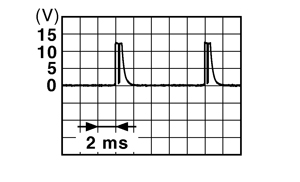
1.3 V |
|||||
|
Front washer switch ON |
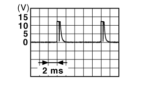
1.3 V |
|||||
|
108 (R) |
Ground |
Combination switch INPUT 4 |
Input |
Combination switch |
All switches OFF (Wiper intermittent dial 4) |
1.4 V |
|
Lighting switch 1ST (Wiper intermittent dial 4) |
1.3 V |
|||||
Any of the conditions below with all switches OFF
|
1.3 V |
|||||
|
109 (Y) |
Ground |
Combination switch INPUT 2 |
Input |
Combination switch (Wiper intermittent dial 4) |
All switches OFF |
1.4 V |
|
Lighting switch PASS |
1.3 V |
|||||
|
Lighting switch 2ND |
1.3 V |
|||||
|
Front wiper switch INT |
1.3 V |
|||||
|
Front wiper switch HI |
1.3 V |
|||||
|
110 (G) |
Ground |
Hazard switch |
Input |
Hazard switch |
Pressed |
0 V |
|
Not pressed |
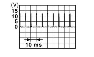
1.1 V |
|||||
|
111 (Y) |
Ground |
Steering lock unit communication |
Input/Output |
Steering lock |
LOCK status |
Battery voltage |
|
LOCK or UNLOCK |
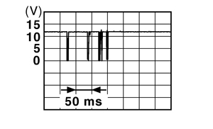
|
|||||
|
For 15 seconds after UNLOCK |
Battery voltage |
|||||
|
15 seconds or later after UNLOCK |
0 V |
|||||
|
116 (SB) |
Ground |
Fuse check (Stop lamp switch) |
Input |
— |
Battery voltage |
|
|
118 (P) |
Ground |
Stop lamp switch |
Input |
Stop lamp switch |
OFF (Brake pedal is not depressed) |
0 V |
|
ON (Brake pedal is depressed) |
Battery voltage |
|||||
|
119 (SB) |
Ground |
Driver side door lock actuator (unlock sensor) |
Input |
Driver door |
LOCK status (unlock sensor switch OFF) |
11.8 V |
|
UNLOCK status (unlock sensor switch ON) |
0 V |
|||||
|
121 (R) |
Ground |
Key slot switch |
Input |
When Intelligent Key is inserted into key slot |
Battery voltage |
|
|
When Intelligent Key is not inserted into key slot |
0 V |
|||||
|
122 (V) |
Ground |
ACC feedback |
Input |
Ignition switch |
OFF |
0 V |
|
ACC or ON |
Battery voltage |
|||||
|
123 (BR) |
Ground |
IGN feedback |
Input |
Ignition switch |
OFF or ACC |
0 V |
|
ON |
Battery voltage |
|||||
|
124 (LG) |
Ground |
Passenger door switch |
Input |
Passenger door switch |
OFF (When passenger door closes) |
11.8 V |
|
ON (When passenger door opens) |
0 V |
|||||
|
128 (P) |
Ground |
Door lock and unlock switch LOCK |
Input |
Door lock and unlock switch (power window main switch or power window sub-switch) |
NEUTRAL position |
11.8 V |
|
LOCK position |
0 V |
|||||
|
129 (O) |
Ground |
Trunk lid opener cancel switch |
Input |
Trunk lid opener cancel switch |
CANCEL |
1.1 V |
|
ON |
0 V |
|||||
|
131 (BR) |
Ground |
Door lock and unlock switch UNLOCK |
Input |
Door lock and unlock switch (power window main switch or power window sub-switch) |
NEUTRAL position |
11.8 V |
|
LOCK position |
0 V |
|||||
|
133 (W) |
Ground |
Push-button ignition switch illumination |
Output |
Push-button ignition switch illumination |
ON (When tail lamps OFF) |
5.5 V |
|
ON (When tail lamps ON) |
NOTE:
The pulse width of this wave is varied by the illumination brightening/dimming level.
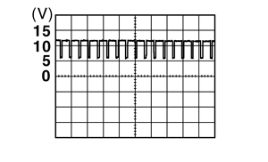
|
|||||
|
OFF |
0 V |
|||||
|
134 (GR) |
Ground |
LOCK indicator lamp |
Output |
LOCK indicator lamp |
ON |
0 V |
|
OFF |
Battery voltage |
|||||
|
137 (L) |
Ground |
Receiver and sensor ground |
Input |
Ignition switch ON |
0 V |
|
|
140 (BR) |
Ground |
Selector lever P/N position |
Input |
Selector lever |
P or N position |
12.0 V |
|
Except P and N positions |
0 V |
|||||
|
141 (G) |
Ground |
Security indicator |
Output |
Security indicator |
ON |
0 V |
|
Blinking |
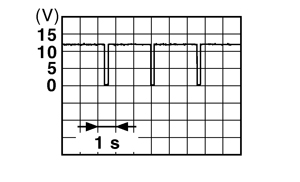
11.3 V |
|||||
|
OFF |
Battery voltage |
|||||
|
142 (O) |
Ground |
Combination switch OUTPUT 5 |
Output |
Combination switch (Wiper intermittent dial 4) |
All switches OFF |
0 V |
|
Lighting switch 1ST |
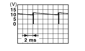
10.7 V |
|||||
|
Lighting switch HI |
||||||
|
Lighting switch 2ND |
||||||
|
Turn signal switch RH |
||||||
|
143 (P) |
Ground |
Combination switch OUTPUT 1 |
Output |
Combination switch |
All switches OFF (Wiper intermittent dial 4) |
0 V |
|
Front wiper switch HI (Wiper intermittent dial 4) |
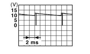
10.7 V |
|||||
Any of the conditions below with all switches OFF
|
||||||
|
144 (G) |
Ground |
Combination switch OUTPUT 2 |
Output |
Combination switch |
All switches OFF (Wiper intermittent dial 4) |
0 V |
|
Front washer switch ON (Wiper intermittent dial 4) |
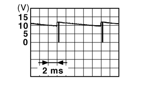
10.7 V |
|||||
Any of the conditions below with all switches OFF
|
||||||
|
145 (L) |
Ground |
Combination switch OUTPUT 3 |
Output |
Combination switch (Wiper intermittent dial 4) |
All switches OFF |
0 V |
|
Front wiper switch INT |
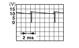
10.7 V |
|||||
|
Front wiper switch LO |
||||||
|
146 (SB) |
Ground |
Combination switch OUTPUT 4 |
Output |
Combination switch (Wiper intermittent dial 4) |
All switches OFF |
0 V |
|
Lighting switch 2ND |
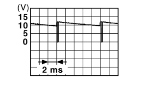
10.7 V |
|||||
|
Lighting switch PASS |
||||||
|
Turn signal switch LH |
||||||
|
150 (GR) |
Ground |
Driver door switch |
Input |
Driver door switch |
OFF (When driver door closes) |
11.8 V |
|
ON (When driver door opens) |
0 V |
|||||
|
151 (G) |
Ground |
Rear window defogger relay |
Output |
Rear window defogger |
Active |
0 V |
|
Not activated |
Battery voltage |
|||||
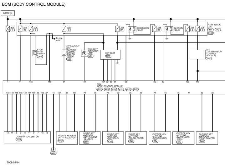
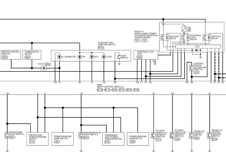
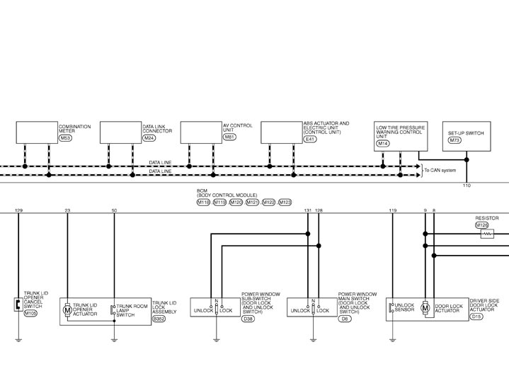
Wiring Diagram - BCM -
Fail-safe
FAIL-SAFE CONTROL BY DTCBCM performs fail-safe control when any DTC are detected.
| Display contents of CONSULT | Fail‐safe | Cancellation |
| B2013: ID DISCORD BCM-S/L | Inhibit engine cranking | Erase DTC |
| B2014: CHAIN OF S/L-BCM | Inhibit engine cranking | Erase DTC |
| B2190: NATS ANTENNA AMP | Inhibit engine cranking | Erase DTC |
| B2191: DIFFERENCE OF KEY | Inhibit engine cranking | Erase DTC |
| B2192: ID DISCORD BCM-ECM | Inhibit engine cranking | Erase DTC |
| B2193: CHAIN OF BCM-ECM | Inhibit engine cranking | Erase DTC |
| B2557: VEHICLE SPEED | Inhibit steering lock | When normal vehicle speed signals are received from ABS actuator and electric unit (control unit) for 500 ms |
| B2560: STARTER CONT RELAY | Inhibit engine cranking | 500 ms after the following CAN signal communication status becomes consistent
|
| B2601: SHIFT POSITION | Inhibit steering lock | 500 ms after the following signal reception status becomes consistent
|
| B2602: SHIFT POSITION | Inhibit steering lock | 5 seconds after the following BCM recognition conditions are fulfilled
|
| B2603: SHIFT POSI STATUS | Inhibit steering lock | 500 ms after the following BCM recognition conditions are fulfilled
|
| B2604: PNP SW | Inhibit steering lock | 500 ms after any of the following BCM recognition conditions are fulfilled
|
| B2605: PNP SW | Inhibit steering lock | 500 ms after any of the following BCM recognition conditions are fulfilled
|
| B2606: S/L RELAY | Inhibit engine cranking | 500 ms after the following CAN signal communication status becomes consistent
|
| B2607: S/L RELAY | Inhibit engine cranking | 500 ms after the following CAN signal communication status becomes consistent
|
| B2608: STARTER RELAY | Inhibit engine cranking | 500 ms after the following signal communication status becomes consistent
|
| B2609: S/L STATUS |
| When the following steering lock conditions agree
|
| B260A: IGNITION RELAY | Inhibit engine cranking | 500 ms after the following conditions are fulfilled
|
| B260F: ENG STATE SIG LOST | Maintains the power supply position attained at the time of DTC detection | When any of the following conditions are fulfilled
|
| B2612: S/L STATUS |
| When any of the following conditions are fulfilled
|
| B2617: STARTER RELAY CIRC | Inhibit engine cranking | 1 second after the starter motor relay control inside BCM becomes normal |
| B2618: BCM | Inhibit engine cranking | 1 second after the ignition relay (IPDM E/R) control inside BCM becomes normal |
| B2619: BCM | Inhibit engine cranking | 1 second after the steering lock unit power supply output control inside BCM becomes normal |
| B261E: VEHICLE TYPE | Inhibit engine cranking | BCM initialization |
| B26E9: S/L STATUS |
| When BCM transmits the LOCK request signal to steering lock unit, and receives LOCK response signal from steering lock unit, the following conditions are fulfilled
|
HIGH FLASHER OPERATIONBCM detects the turn signal lamp circuit status by the current value.
BCM increases the turn signal lamp blinking speed if the bulb or harness open is detected with the turn signal lamp operating.
NOTE:
The blinking speed is normal while activating the hazard warning lamp.DTC Inspection Priority Chart
If some DTCs are displayed at the same time, perform inspections one by one based on the following priority chart.
| Priority | DTC |
| 1 | B2562: LOW VOLTAGE |
| 2 |
|
| 3 |
|
| 4 |
|
| 5 |
|
| 6 | B26E7: TPMS CAN COMM |
DTC Index
NOTE:
The details of time display are as follows.- CRNT: A malfunction is detected now.
- PAST: A malfunction was detected in the past.
|
CONSULT display |
Fail-safe |
Freeze Frame Data
|
Intelligent Key warning lamp ON |
Reference page |
|
No DTC is detected. Further testing may be required. |
— |
— |
— |
— |
|
U1000: CAN COMM CIRCUIT |
— |
— |
— |
Description
|
|
U1010: CONTROL UNIT (CAN) |
— |
— |
— |
DTC Logic
|
|
U0415: VEHICLE SPEED SIG |
— |
— |
— |
Description
|
|
B2013: ID DISCORD BCM-S/L |
× |
× |
— |
Description
|
|
B2014: CHAIN OF S/L-BCM |
× |
× |
— |
Description
|
|
B2190: NATS ANTENNA AMP |
× |
— |
— |
Description
|
|
B2191: DIFFERENCE OF KEY |
× |
— |
— |
Description
|
|
B2192: ID DISCORD BCM-ECM |
× |
— |
— |
Description
|
|
B2193: CHAIN OF BCM-ECM |
× |
— |
— |
Description
|
|
B2553: IGNITION RELAY |
— |
× |
— |
Description
|
|
B2555: STOP LAMP |
— |
× |
— |
Description
|
|
B2556: PUSH-BTN IGN SW |
— |
× |
× |
Description
|
|
B2557: VEHICLE SPEED |
× |
× |
× |
Description
|
|
B2560: STARTER CONT RELAY |
× |
× |
× |
Description
|
|
B2562: LOW VOLTAGE |
— |
× |
— |
DTC Logic
|
|
B2601: SHIFT POSITION |
× |
× |
× |
Description
|
|
B2602: SHIFT POSITION |
× |
× |
× |
Description
|
|
B2603: SHIFT POSI STATUS |
× |
× |
× |
Description
|
|
B2604: PNP SW |
× |
× |
× |
Description
|
|
B2605: PNP SW |
× |
× |
× |
Description
|
|
B2606: S/L RELAY |
× |
× |
× |
Description
|
|
B2607: S/L RELAY |
× |
× |
× |
Description
|
|
B2608: STARTER RELAY |
× |
× |
× |
Description
|
|
B2609: S/L STATUS |
× |
× |
× |
Description
|
|
B260A: IGNITION RELAY |
× |
× |
× |
Description
|
|
B260B: STEERING LOCK UNIT |
— |
× |
× |
Description
|
|
B260C: STEERING LOCK UNIT |
— |
× |
× |
Description
|
|
B260D: STEERING LOCK UNIT |
— |
× |
× |
Description
|
|
B260F: ENG STATE SIG LOST |
× |
× |
× |
Description
|
|
B2612: S/L STATUS |
× |
× |
× |
Description
|
|
B2614: ACC RELAY CIRC |
— |
× |
× |
Description
|
|
B2615: BLOWER RELAY CIRC |
— |
× |
× |
Description
|
|
B2616: IGN RELAY CIRC |
— |
× |
× |
Description
|
|
B2617: STARTER RELAY CIRC |
× |
× |
× |
Description
|
|
B2618: BCM |
× |
× |
× |
Description
|
|
B2619: BCM |
× |
× |
× |
Description
|
|
B261A: PUSH-BTN IGN SW |
— |
× |
× |
Description
|
|
B261E: VEHICLE TYPE |
× |
× |
× (Turn ON for 15 seconds) |
Description
|
|
B2621: INSIDE ANTENNA |
— |
× |
— |
Description
|
|
B2622: INSIDE ANTENNA |
— |
× |
— |
Description
|
|
B2623: INSIDE ANTENNA |
— |
× |
— |
Description
|
|
B26E7: TPMS CAN COMM |
— |
— |
— |
DTC Logic
|
|
B26E9: S/L STATUS |
× |
× |
× (Turn ON for 15 seconds) |
Description
|
|
B26EA: KEY REGISTRATION |
— |
× |
× (Turn ON for 15 seconds) |
Description
|