TRANSMISSION SYSTEM
TRANSMISSION: GR6Z30A
Operation Status and Control
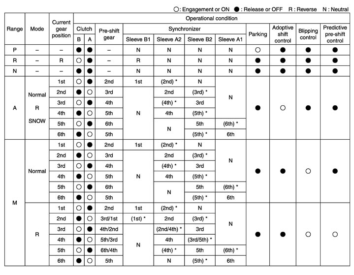
*: Pre-shift (pre-shift means that the gear on the clutch release side shifts to the next speed before a gear shift occurs.)
Main Device
 DUAL CLUTCH
- It is equipped with 2 wet clutches, clutch A and clutch B, and each clutch is engaged or released by the hydraulic piston.
- If there is no oil pressure, the return spring forces the piston to return, releasing the clutch.
SHIFT DEVICE- Each synchronizer is activated by its own shift actuator (hydraulic cylinder).
- Borg Warner type triple cone synchronizer is used for all the gear speeds.
- A friction material is affixed to the cone surface of the synchronizer to allow higher capacity than a normal cone made of copper alloy.
- The actuator control module is a unit integrated with the shift actuator and hydraulic control valve.
SHIFT LEVER- It inputs the range position (P, R, N, A ⇔ M) and Auto/Manual range change switch signal to the TCM.
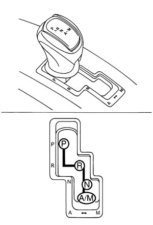
- It is connected to the parking device of the transmission with the control cable, and it locks the parking device only when the shift lever is shifted into the P position.
PADDLE SHIFTERIt inputs the switch signal of upshift or downshift to TCM.
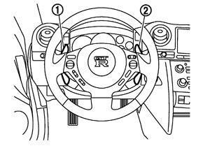
| 1 | : Paddle shifter (shift-down switch) |
| 2 | : Paddle shifter (shift-up switch) |
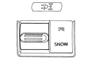
SET-UP SWITCH (TRANSMISSION)It inputs the switch signal of R mode or SNOW mode to TCM.
 DISPLAY DEVICE
 Information display
|
Message content |
Display timing |
Erasure procedure |
Remarks |
|
T/M SYSTEM MALFUNCTION VISIT DEALER |
When the check is necessary |
|
Always blink the transmission warning light when this message is displayed |
|
SHIFT TO THE P RANGE |
|
Shift the shift lever to the P range |
— |
|
CHECK POSITION OF SHIFT LEVER |
When the shift lever position cannot be detected |
Shift the shift lever into either range of P, R, N, A ⇔ M |
— |
|
T/M SYSTEM CHECK IN PROCESS |
When the diagnosis is performed just after the engine starts while the shift lever is in the P range |
Wait for a short period of time until the diagnosis is completed |
While this message is displayed, the shift lock solenoid prevents the shift lever from moving out of the P range |
|
T/M OIL TEMP HIGH DECREASE SPEED |
When the high oil temperature control is active because of high transmission fluid temperature |
When the high oil temperature control is deactivated |
Always illuminate the transmission warning light when this message is displayed |
|
T/M CLUTCH TEMP HIGH STOP VEHICLE UNTIL WARNING TURNS OFF |
When the clutch protection control is active because of high clutch temperature or stall driving |
When the clutch protection control is deactivated |
Always illuminate the transmission warning light when this message is displayed |
Shift position indicatorUpon receiving the CAN output signal from TCM, the drive gear position appears and blinks, and the range is displayed.
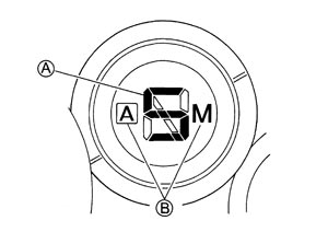
| A | : Range position and drive gear position (A/M range) |
| B | : A range or M range |
Transmission warning lightIt illuminates and blinks with the CAN output signal from TCM.
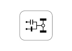
| ON | : It shows an intermittent malfunction such as high transmission fluid temperature. |
| Blinking | : It shows that a malfunction requiring a check occurs. |
Mode indicatorR mode lamp and SNOW mode lamp illuminate by the analog output signal from TCM.
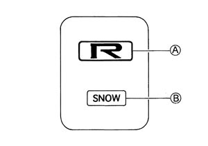
| A | : R mode lamp |
| B | : SNOW mode lamp |
Multi-function displayThe drive gear position, range position, transmission oil pressure and transmission oil temperature are displayed by the CAN output signal from TCM.
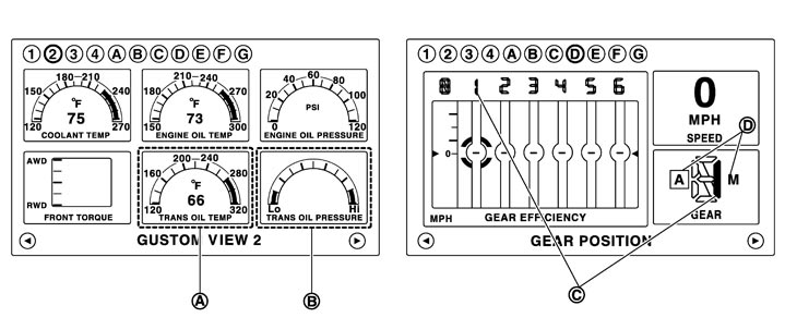
| A. | Transmission oil temperature | B. | Transmission oil pressure | C. | Range position and drive gear position (A/M range) |
| D. | A range or M range |
Oil Pressure System
COMPONENT DESCRIPTION|
Component |
Function |
||
|
Suction filter |
Removes foreign matter contained in fluid and prevents them from entering the hydraulic circuit |
||
|
Inline filter |
|||
|
Heat exchanger |
|
||
|
Front control module |
Oil pump |
Sucks fluid accumulated in the oil pan to build up oil pressure in the circuit |
|
|
Valve |
Line pressure valve |
|
|
|
Clutch A solenoid valve |
Controls the clutch pressure of clutch A/B |
||
|
Clutch B solenoid valve |
|||
|
Lubricating flow valve |
|
||
|
Clutch lubricating switching valve |
Switches the lubricating distribution of the clutch. |
||
|
Pressure sensor |
Clutch A pressure sensor |
Detects the clutch pressure of clutch A/B |
|
|
Clutch B pressure sensor |
|||
|
Actuator control module |
Valve |
Axis A feed pressure valve |
|
|
Axis B feed pressure valve |
|||
|
Shift solenoid valve 1 |
Controls 4 shift actuator pistons by combining ON and OFF of each shift solenoid valve and switching the sequence valve circuit |
||
|
Shift solenoid valve 2 |
|||
|
Shift solenoid valve 3 |
|||
|
Shift solenoid valve 4 |
|||
|
Sequence valve |
|||
|
Pressure sensor |
Line pressure sensor |
Detects the line pressure |
|
TCM System
WIRING DIAGRAM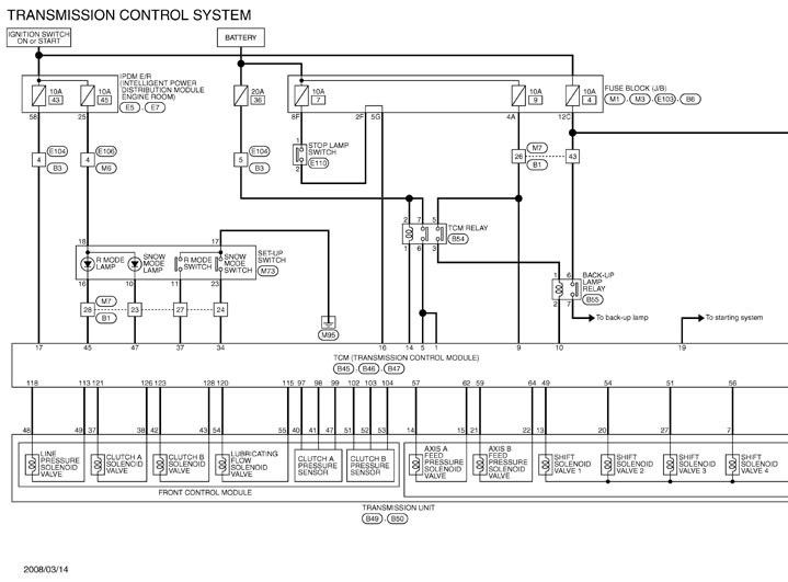
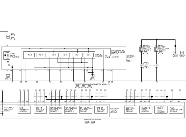
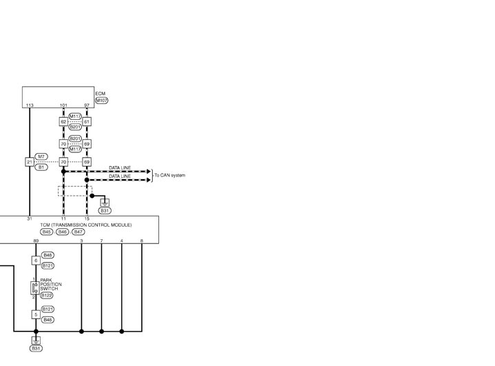 COMPONENT DESCRIPTION
|
Component |
Function |
|||
|
Front control module |
Valve |
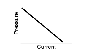
Line pressure solenoid valve |
Controls the line pressure by the line pressure solenoid current |
|
|
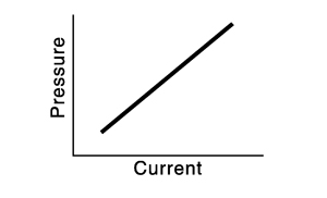
Clutch A solenoid valve |
Controls the clutch pressure of clutches A/B by the clutch A/B solenoid current |
|
||
|
Clutch B solenoid valve |
||||
|
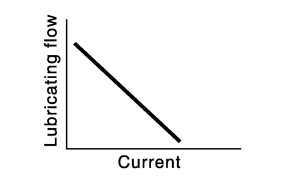
Lubricating flow solenoid valve |
Controls the lubricating flow by the lubricating flow solenoid current |
|
||
|
Pressure sensor |
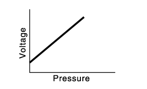
Clutch A pressure sensor |
Converts the clutch pressure of clutches A/B into voltage |
|
|
|
Clutch B pressure sensor |
||||
|
Actuator control module |
Valve |
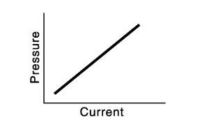
Axis A feed pressure solenoid valve |
Controls the feed pressure of axes A/B by the axes A/B feed pressure solenoid |
|
|
Axis B feed pressure solenoid valve |
||||
|
Shift solenoid valve 1 |
Controls 4 shift actuator pistons by combining ON and OFF of each shift solenoid valve*1 |
|||
|
Shift solenoid valve 2 |
||||
|
Shift solenoid valve 3 |
||||
|
Shift solenoid valve 4 |
||||
|
Sequence solenoid valve |
||||
|
Pressure sensor |
Line pressure sensor |
Converts the line pressure into voltage |
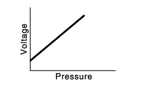
|
|
|
Position sensor |
1st-Reverse position sensor 1 |
|
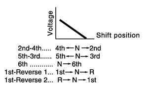
|
|
|
1st-Reverse position sensor 1 |
||||
|
2nd-4th position sensor |
||||
|
6th-Neutral position sensor |
||||
|
3rd-5th position sensor |
||||
|
Wheel sensor |
Clutch A speed sensor |
Converts the clutches A/B speed into pulse |
||
|
Clutch B speed sensor |
||||
|
Output shaft speed sensor |
Converts the output shaft speed into pulse |
|||
|
Park position switch |
When the parking position is locked, it is energized, and when unlocked, it is not energized |
|||
|
Fluid temperature sensor |
Converts the oil pan oil temperature into electrical resistance |
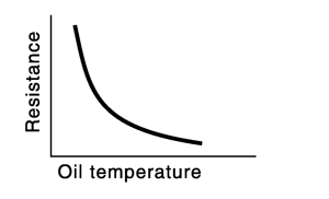
|
||
|
TCM |
Controls the transmission system |
|||
|
Shift device |
Range sensor |
Range sensor No. 0 |
With 6 range sensors, the shift lever position is recognized*2 |
|
|
Range sensor No. 1 |
||||
|
Range sensor No. 2 |
||||
|
Range sensor No. 3 |
||||
|
Range sensor No. 4 |
||||
|
Range sensor No. 5 |
||||
|
Auto/Manual range change switch |
Inputs the Auto/Manual range change switch signal to TCM |
|||
|
Shift lock solenoid |
Lock or unlock is attained with 3 systems, the ignition switch signal, stop lamp switch signal and lock or unlock signal (TCM) |
|||
|
Set-up switch |
R mode switch |
Normally not energized, and energized by turning the set-up switch to R |
||
|
SNOW mode switch |
Normally not energized, and energized by turning the set-up switch to SNOW |
|||
|
TCM relay |
Perform the power supply to TCM |
|||
Shift actuator operation list
| Shift actuator | Operation | Solenoid valve | ||||
| Sequence | Shift 1 | Shift 2 | Shift 3 | Shift 4 | ||
| 6th-Neutral shift actuator | 6th gear → N | ON | ON | OFF | – | – |
| 6th gear ← N | OFF | ON | – | – | ||
| 2nd-4th shift actuator | 2nd gear → N → 4th gear | OFF | ON | OFF | – | – |
| 2nd gear ← N ← 4th gear | OFF | ON | – | – | ||
| 3rd-5th shift actuator | 5th gear → N → 3rd gear | ON | – | – | OFF | ON |
| 5th gear ← N ← 3rd gear | – | – | ON | OFF | ||
| 1st-Reverse shift actuator | 1st gear → N → Reverse | OFF | – | – | ON | OFF |
| 1st gear ← N ← Reverse | – | – | OFF | ON | ||
Shift lever position and range sensor output
|
Shift lever position |
Range sensor |
|||||
|
No. 0 |
No. 1 |
No. 2 |
No. 3 |
No. 4 |
No. 5 |
|
|
P |
ON |
OFF |
OFF |
OFF |
OFF |
OFF |
|
R |
OFF |
ON |
ON |
OFF |
OFF |
OFF |
|
N |
OFF |
OFF |
ON |
ON |
ON |
OFF |
|
A⇔M |
OFF |
OFF |
OFF |
OFF |
ON |
ON |
Component Parts Location
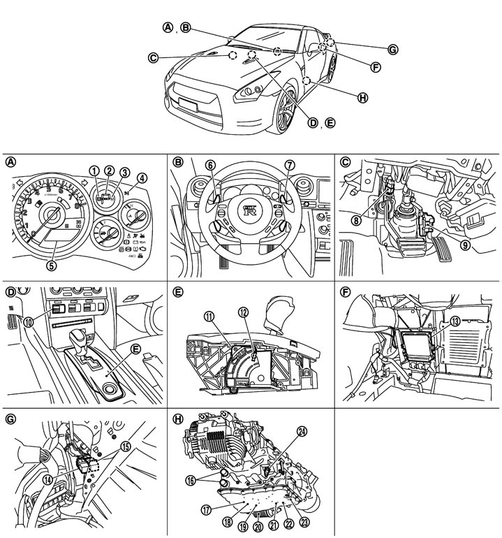
|
1. |
A range indicator |
2. |
Shift position indicator |
3. |
M range indicator |
|
4. |
Transmission warning light |
5. |
Information display |
6. |
Paddle shifter (shift-down switch) |
|
7. |
Paddle shifter (shift-up switch) |
8. |
Stop lamp switch |
9. |
Accelerator pedal position sensor |
|
10. |
Set-up switch |
11. |
Range sensor |
12. |
Auto/Manual range change switch |
|
13. |
TCM |
14. |
TCM relay |
15. |
Back-up lamp relay |
|
16. |
Transmission connector |
17. |
Output shaft speed sensor |
18. |
Clutch A speed sensor |
|
19. |
Clutch B speed sensor |
20. |
Heat exchanger |
21. |
Actuator control module |
|
22. |
Fluid temperature sensor |
23. |
Front control module |
24. |
Park position switch |
|
A. |
Combination meter |
B. |
Steering assembly |
C. |
Rear of LH instrument lower panel |
|
D. |
Center console |
E. |
Control device assembly |
F. |
Trunk room |
|
G. |
Left side of trunk room |
H. |
Transmission assembly |
|
|
|
The following parts are integrated into the actuator control module (21). |
|||||
|
|
Axis A feed pressure solenoid valve |
|
Axis B feed pressure solenoid valve |
|
Shift solenoid valve 1 |
|
|
Shift solenoid valve 2 |
|
Shift solenoid valve 3 |
|
Shift solenoid valve 4 |
|
|
Sequence solenoid valve |
|
Line pressure sensor |
|
1st-Reverse position sensor 1 |
|
|
1st-Reverse position sensor 1 |
|
2nd-4th position sensor |
|
6th-Neutral position sensor |
|
|
3rd-5th position sensor |
|
|
|
|
|
The following parts are integrated into the front control module (23). |
|||||
|
|
Line pressure solenoid valve |
|
Clutch A solenoid valve |
|
Clutch B solenoid valve |
|
|
Lubricating flow solenoid valve |
|
Clutch A pressure sensor |
|
Clutch B pressure sensor |