 1.CHECK FOR INTAKE AIR LEAK AND PCV HOSE
- Start engine and run it at idle speed.
- Listen for the sound of the intake air leak.
- Check PCV hose connection.
Is intake air leak detected?
YES >>Discover air leak location and repair. NO >>GO TO 2.
2.CHECK FOR EXHAUST SYSTEM CLOGGING
Stop engine and visually check exhaust tube, three way catalyst and muffler for dents. Is the inspection result normal? YES-1 >>With CONSULT-III: GO TO 3. YES-2 >>Without CONSULT-III: GO TO 4. NO >>Repair or replace malfunctioning part.
3.PERFORM POWER BALANCE TEST
 With CONSULT-III
- Start engine.
- Perform “POWER BALANCE” in “ACTIVE TEST” mode with CONSULT-III.
- Check that each circuit produces a momentary engine speed drop.
Is the inspection result normal?
YES >>GO TO 9. NO >>GO TO 4.
4.CHECK FUNCTION OF FUEL INJECTOR-I
5.CHECK FUNCTION OF IGNITION COIL-I
■ CAUTION ■
Perform the following procedure in a place with no combustible objects and good ventilation.
- Turn ignition switch OFF.
- Remove fuel pump fuse (1) in IPDM E/R (2) to release fuel pressure.
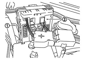
NOTE: Do not use CONSULT-III to release fuel pressure, or fuel pressure applies again during the following procedure.
- Start engine.
- After engine stalls, crank it two or three times to release all fuel pressure.
- Turn ignition switch OFF.
- Remove all ignition coil harness connectors to avoid the electrical discharge from the ignition coils.
- Remove ignition coil and spark plug of the cylinder to be checked.
- Crank engine for 5 seconds or more to remove combustion gas in the cylinder.
- Connect spark plug and harness connector to ignition coil.
- Fix ignition coil using a rope etc. with gap of 13 - 17 mm (0.52 - 0.66 in) between the edge of the spark plug and grounded metal portion as shown in the figure.
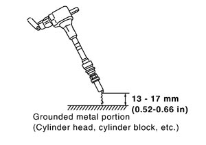
- Crank engine for about 3 seconds, and check whether spark is generated between the spark plug and the grounded metal portion.
Spark should be generated.
|
■ CAUTION ■ - Never place to the spark plug and the ignition coil within 50 cm (19.7 in) each other. Be careful not to get an electrical shock while checking, because the electrical discharge voltage becomes 20 kV or more.
- It might cause to damage the ignition coil if the gap of more than 17 mm (0.66 in) is made.
NOTE: When the gap is less than 13 mm (0.52 in), a spark might be generated even if the coil is malfunctioning.
Is the inspection result normal?
YES >>GO TO 9. NO >>GO TO 6.
6.CHECK FUNCTION OF IGNITION COIL-II
- Turn ignition switch OFF.
- Disconnect spark plug and connect a non-malfunctioning spark plug.
- Crank engine for about 3 seconds, and recheck whether spark is generated between the spark plug and the grounded metal portion.
Spark should be generated.
|
Is the inspection result normal?
YES >>GO TO 7. NO >>Check ignition coil, power transistor and their circuits. Refer to Diagnosis Procedure (GT-R certified NISSAN dealer).
7.CHECK SPARK PLUG
Check the initial spark plug for fouling, etc. 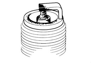 Is the inspection result normal? YES >>Replace spark plug(s) with standard type one(s). For spark plug type, refer to Spark Plug (GT-R certified NISSAN dealer). NO >>Repair or clean spark plug. Then GO TO 8.
8.CHECK FUNCTION OF IGNITION COIL-III
- Reconnect the initial spark plugs.
- Crank engine for about 3 seconds, and recheck whether spark is generated between the spark plug and the grounded portion.
Spark should be generated.
|
Is the inspection result normal?
YES >>INSPECTION END NO >>Replace spark plug(s) with standard type one(s). For spark plug type, refer to Spark Plug (GT-R certified NISSAN dealer).
9.CHECK COMPRESSION PRESSURE
10.CHECK FUEL PRESSURE
11.DETECT MALFUNCTIONING PART
Check fuel hoses and fuel tubes for clogging. Is the inspection result normal? YES >>Replace “fuel filter and fuel pump assembly”. NO >>Repair or replace malfunctioning part.
12.CHECK IDLE SPEED AND IGNITION TIMING
13.CHECK A/F SENSOR 1 INPUT SIGNAL CIRCUIT
- Turn ignition switch OFF.
- Disconnect corresponding A/F sensor 1 harness connector.
- Disconnect ECM harness connector.
- Check the continuity between A/F sensor 1 harness connector and ECM harness connector.
A/F sensor 1
| ECM
| Continuity
| Bank
| Connector
| Terminal
| Connector
| Terminal
| 1
| F8
| 1
| F102
| 81
| Existed
| 2
| 82
| 2
| F25
| 1
| 85
| 2
| 86
|
- Check the continuity between A/F sensor 1 harness connector or ECM harness connector and ground.
A/F sensor 1
| ECM
| Ground
| Continuity
| Bank
| Connector
| Terminal
| Connector
| Terminal
| 1
| F8
| 1
| F102
| 81
| Ground
| Not existed
| 2
| 82
| 2
| F25
| 1
| 85
| 2
| 86
|
- Also check harness for short to power.
Is the inspection result normal?
YES >>GO TO 14. NO >>Repair open circuit, short to ground or short to power in harness or connectors.
14.CHECK A/F SENSOR 1 HEATER
15.CHECK MASS AIR FLOW SENSOR
16.CHECK SYMPTOM MATRIX CHART
17.ERASE THE 1ST TRIP DTC
18.CHECK INTERMITTENT INCIDENT
|