 CONTROL OPERATION
 A/C Display
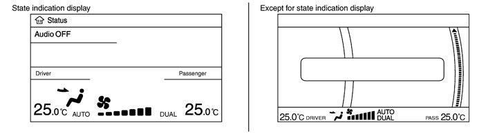
- The status display screen is displayed by pressing the STATUS switch to check the A/C system operating condition.
- If the A/C operation is performed when any screen other than the status display screen (such as the navigation system and the audio system) is displayed, the switch operating condition of the used switch is displayed on the bottom of the screen. It turns OFF automatically after several seconds.
Controller (Preset Switch)
MODE Switch
- The “AUTO” on the A/C display turns OFF by pressing the MODE switch from the condition that the AUTO switch is ON (automatic control).
- The set temperature (driver side and passenger side) and air outlets are displayed on the A/C display by pressing the MODE switch from the condition that the A/C system is OFF. At this time, the display area may be changed depending on the DUAL switch condition (ON-OFF) before the system is OFF.
- The air outlets may be switched by pressing the MODE switch. Any of VENT, B/L, FOOT, or D/F can be selected. VENT→B/L→FOOT→D/F→VENT
Temperature Control Dial (Potentio Temperature Control)
- It can select the set temperature of A/C display at the range of 18.0°C (60°F) to 32.0°C (90°F) in increments of 0.5°C (1.0°F) freely.
- It increases in increments of 0.5°C (1.0°F) by turning the temperature control dial clockwise.
- It decreases in increments of 0.5°C (1.0°F) by turning the temperature control dial counterclockwise.
- The system is set to the LH/RH independent condition (the DUAL switch indicator turns ON) by operating the temperature control dial (passenger side). It can change the air flow temperature of passenger side without changing the air flow temperature of driver side.
- When the air outlet is set to DEF, the temperature control dial (passenger side) is inoperative.
- The set temperature is changed by operating the temperature control dial even if the A/C system is OFF condition. However, the set temperature is not displayed when the display is turned OFF.
Fan Control Dial
- The fan speed can be selected from the range of 1-7 freely by operating the fan control dial.
- The set temperature, air outlets, and fan speed are displayed on the A/C display by turning the fan control dial clockwise from the condition that the A/C system is OFF.
- The “AUTO” on the A/C display turns OFF by operating the fan control dial from the condition that the AUTO switch is ON (automatic control).
A/C Switch
- “A/C OFF” is displayed on the A/C display for several seconds, the A/C switch indicator turns OFF, and the compressor is turned OFF by pressing the A/C switch from the condition that the compressor is ON (automatic control).
- When pressing the A/C switch again, “A/C ON” is displayed on the A/C display for several seconds, the A/C switch indicator turns ON, and the compressor is turned to ON.
DEF Switch
- The “AUTO” on the A/C display turns OFF and the DEF switch indicator turns ON by pressing the DEF switch from the condition that the AUTO switch is ON (automatic control).
- The set temperature, air outlets (DEF), and fan speed are displayed on the A/C display by pressing the DEF switch from the condition that the A/C system is OFF. The DEF switch indicator and the A/C switch indicator illuminate.
- Basically, pressing the DEF switch fixes the air outlet to DEF and the air inlets to fresh air intake. The FRE switch indicator illuminates, the compressor is turned to ON, and the air flow is set to automatic control. (If the condition before pressing the DEF switch is the air flow manual control, it is not set to the automatic control.)
- When pressing the DEF switch again, it returns to the condition that existed before pressing the switch. However, the air flow manual control is given priority to when the DEF switch is pressed again since the fan control dial is operated after the DEF switch is pressed once. In addition, the air flow manual selection is given priority when the DEF switch is pressed again since the fan switch is operated after starting with the DEF switch from the OFF condition. The air outlets and the air inlets are controlled automatically and the compressor is still ON.
AUTO Switch
- The AUTO switch indicator turns ON. “AUTO”, set temperature (driver side and passenger side), fan speed, and air outlets are displayed on the A/C display.
- The air outlets, air inlets, fan speed, and air flow temperature are controlled automatically. (They are set to the automatic control only when the air inlets are not fixed to recirculation and fresh air intake.)
DUAL Switch
- When the DUAL switch indicator is ON, the driver side and passenger side, temperature can each be set independently.
- When the DUAL switch indicator is OFF, the driver side setting temperature is applied to both sides.
- The left and right ventilation temperature separately control is cancelled by turning the DEF switch to ON.
Recirculation (REC) Switch
- When pressing the REC switch, the REC switch indicator illuminates and the air inlet is fixed to recirculation.
- The REC switch indicator blink twice and the system is switched to the automatic control when pressing the FRE switch or the REC switch for approximately 2 seconds or more. In addition, the condition of the air inlet is displayed at the automatic control.
- When FRE switch indicator turned ON, shifting mode position to D/F or DEF, or when compressor is turned from ON to OFF, REC switch is automatically turned OFF (fixed to fresh air intake). Recirculation mode can be re-entered by pressing REC switch again, and then compressor is turned ON (Except D/F or DEF position).
Fresh (FRE) Switch
- When pressing the FRE switch, the FRE switch indicator illuminates and the air inlet is fixed to fresh air intake.
- The REC switch indicator blink twice and the system is switched to the automatic control when pressing the FRE switch or the REC switch for approximately 2 seconds or more. In addition, the condition of the air inlet is displayed at the automatic control.
Rear Window Defogger Switch
- The “Rear defrost ON” is displayed on the A/C display when pressing the rear window defogger switch. The indicator of rear window defogger switch illuminates, and then the rear window defogger is turned ON.
- The “Rear defrost OFF” is displayed on the A/C display when pressing the rear window defogger switch again. The indicator of rear window defogger switch turns OFF, and then the rear window defogger is turned OFF.
- Refer to System Description for details.
OFF Switch
- The blower motor and compressor are turned OFF when pressing the OFF switch. At this time, the switch condition just before OFF is recorded on the set temperature and the left and right ventilation temperature separately control mode.
- Fix the air inlet to fresh air intake. However, when the REC switch was ON, fix it to recirculation. Inlet status is displayed by indicator when air conditioner system is OFF.
- Set the air outlet to foot position. (The air outlet can be switched with the MODE switch.)
DISCHARGE AIR FLOW
AIR DISTRIBUTION
SWITCHES AND THEIR CONTROL FUNCTION
AIR CONDITIONER LAN CONTROL SYSTEM
The LAN (Local Area Network) system consists of A/C auto amp., mode door motor, air mix door motors and intake door motor. A configuration of these components is as shown in the figure below. 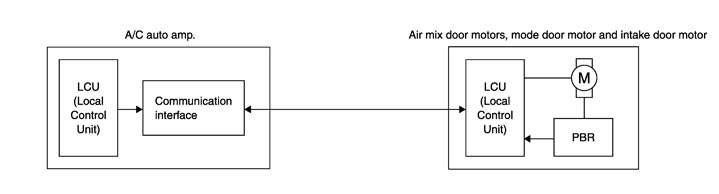
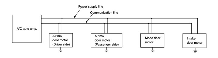
SYSTEM CONSTRUCTION
A small network is constructed between the A/C auto amp., mode door motor, air mix door motors and intake door motor. The A/C auto amp. and motors are connected by data transmission lines and motor power supply lines. The LAN network is built through the ground circuits of each door motor. Addresses, motor opening angle signals, motor stop signals and error checking messages are all transmitted through the data transmission lines connecting the A/C auto amp. and each door motor. The following functions are contained in LCUs built into the mode door motor, the air mix door motors and the intake door motor. - Address
- Motor opening angle signals
- Data transmission
- Motor stop and drive decision
- Opening angle sensor (PBR function)
- Comparison
- Decision (A/C auto amp. indicated value and motor opening angle comparison)
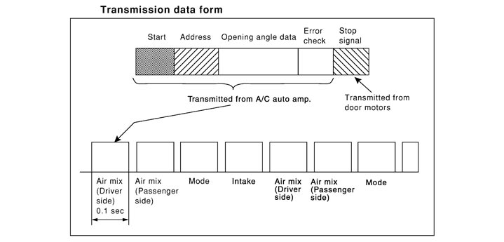
 Operation The A/C auto amp. receives data from each of the sensors. The A/C auto amp. sends mode door, air mix door and intake door opening angle data to the mode door motor LCU, air mix door motor LCUs and intake door motor LCU. The mode door motor, air mix door motors and intake door motor read their respective signals according to the address signal. Opening angle indication signals received from the A/C auto amp. and each of the motor position sensors is compared by the LCUs in each door motor with the existing decision and opening angles. Subsequently, HOT/COLD, DEF/VENT and FRE/REC operation is selected. The new selection data is returned to the A/C auto amp. 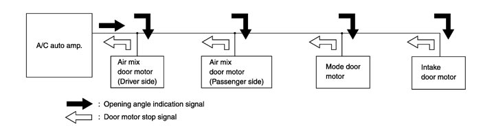 Transmission Data and Transmission Order A/C auto amp. data is transmitted consecutively to each of the doors motor following the form as shown in the figure below.
START:
- Initial compulsory signal is sent to each of the door motors.
ADDRESS:
- Data sent from the A/C auto amp. are selected according to data‐based decisions made by the mode door motor, air mix door motors and intake door motor.
- If the addresses are identical, the opening angle data and error check signals are received by the door motor LCUs. The LCUs then make the appropriate error decision. If the opening angle data have no error, door control begins.
- If an error exists, the received data are rejected and corrected data received. Finally, door control is based upon the corrected opening angle data.
OPENING ANGLE:
- Data that shows the indicated door opening angle of each door motor.
ERROR CHECK:
- In this procedure, transmitted and received data is checked for errors. Error data are then compiled. The error check prevents corrupted data from being used by the mode door motor, the air mix door motors and the intake door motor. Error data can be related to the following symptoms.
- Malfunction of electrical frequency
- Poor electrical connections
- Signal leakage from transmission lines
- Signal level fluctuation
STOP SIGNAL:
- At the end of each transmission, a stop operation, in‐operation, or internal malfunction message is delivered to the A/C auto amp. This completes one data transmission and control cycle.
|