The engine must be removed from the vehicle to remove the cylinder heads. Although it is physically possible (on some models) to remove the cylinder heads with the engine installed, head gasket failure will result upon installation, due to misalignment of the cylinders. The cylinder heads should be removed with the engine cold to prevent warpage.
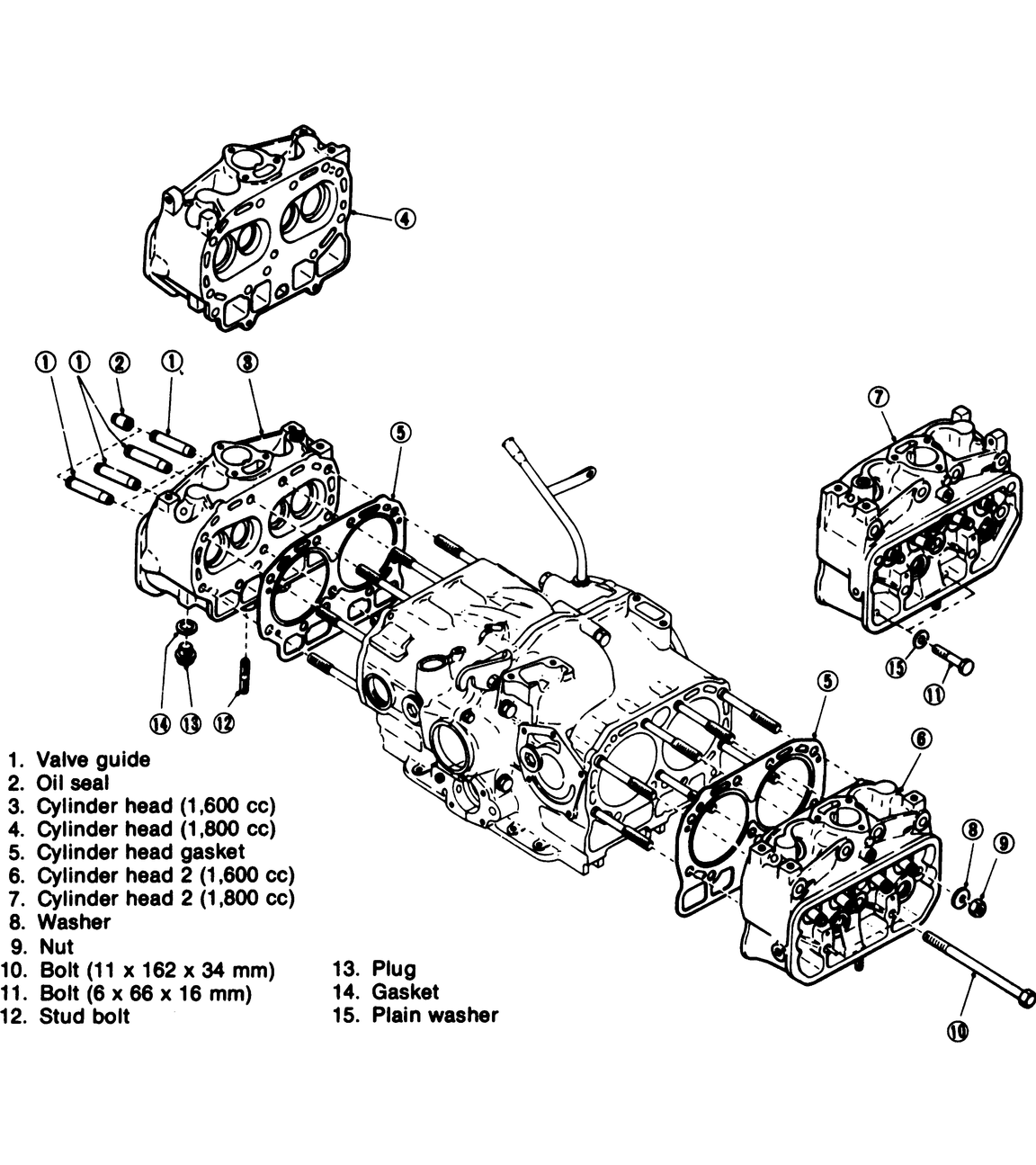
| Fig. 1: Exploded view of a common cylinder head found
on Subarus
|
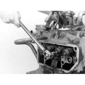
| Fig. 2: Loosen the head bolts in the reverse order
of the tightening sequence . . .
|
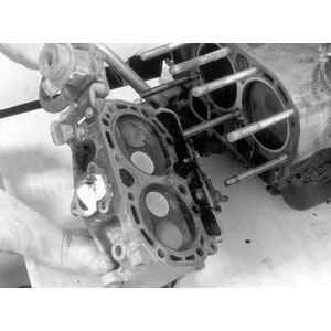
| Fig. 3: . . . then remove the head from the engine
|
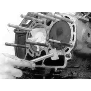
| Fig. 4: Clean the old gasket from both mating surfaces
|
NOTE: Move or disconnect any engine wiring that might impair intake manifold removal.
NOTE: If the pushrods are to be reused, keep them in order so that they are installed in the original positions. The pushrods for all engines are identified by knurling (or the absence of knurling). If you are replacing pushrods, make sure knurled patterns are similar or that unmarked pushrods are replaced by unmarked rods. Markings vary from year to year. For example, for 1981 and 1982, 1800cc OHV engines used pushrods with two knurled marks, while 1983–84 engines have 2 knurled marks for 1600cc engines, a single mark for solid lifter, 1800 engines, and no markings for hydraulic lifter engines.
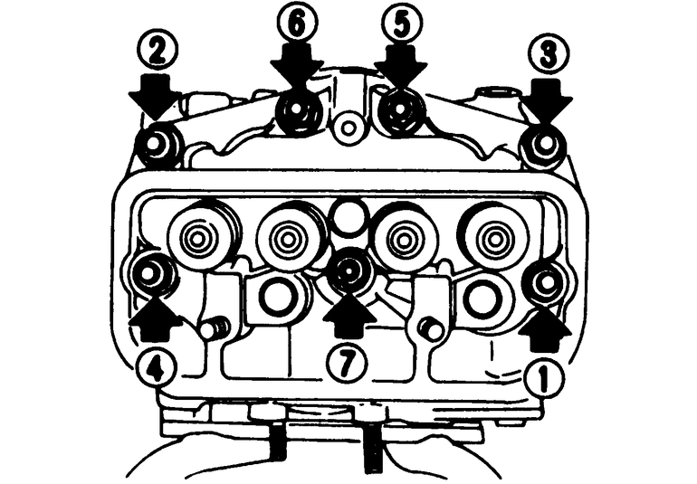
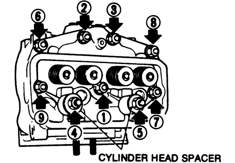
| Fig. 5: Loosening sequence of cylinder head bolts — ff–1
models. Use the reverse of this sequence to tighten the bolts
|
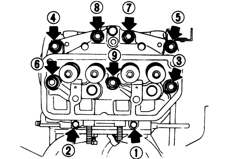
| Fig. 6: Loosening sequence for cylinder head bolts — 1980
models
|
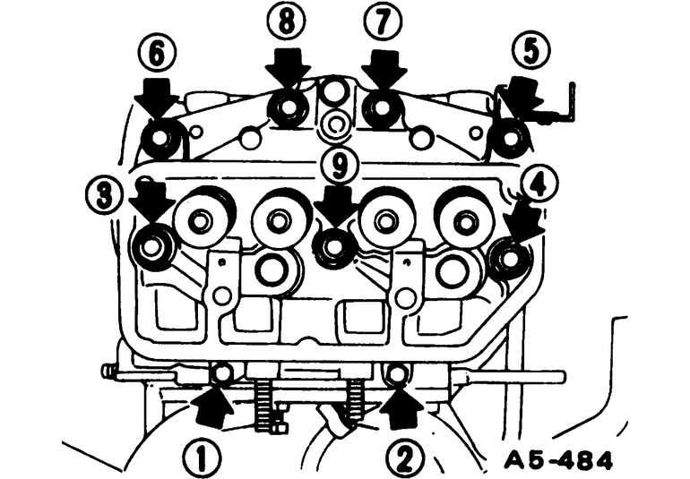
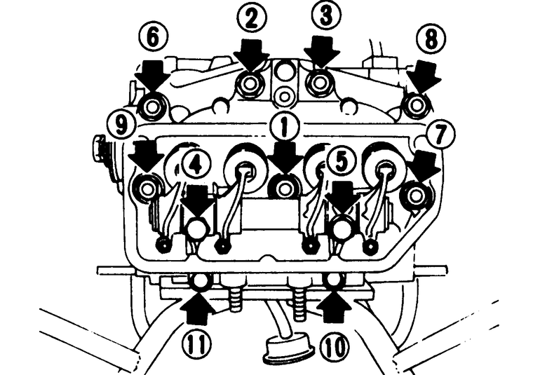
| Fig. 7: Loosening sequence for cylinder head bolts — 1981
models
|
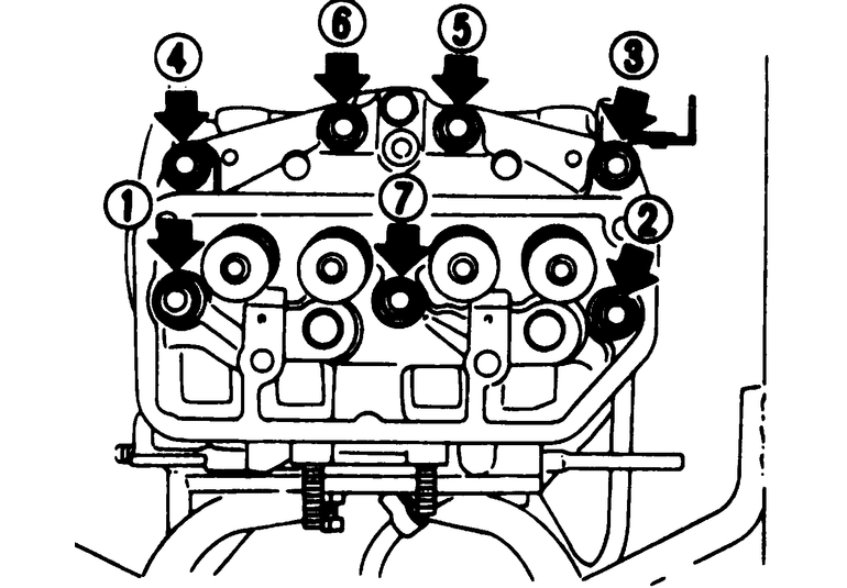
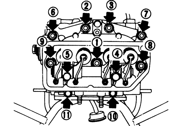
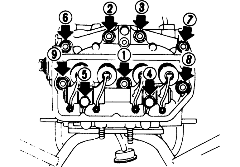
| Fig. 8: Loosening sequence for cylinder head bolts — 1982–84
models
|
To install:
NOTE: The cylinder heads must installed with the cylinders vertical, to avoid misalignment, and to permit the head gasket to crush evenly around the cylinder.
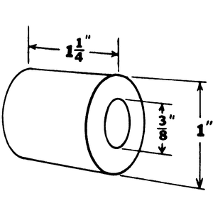
| Fig. 9: Make a cylinder head spacer as shown
|
| Fig. 10: Tightening sequence of cylinder head bolts — 1970–79
models (except ff-1)
|
| Fig. 11: Tightening sequence of cylinder head bolts — 1980
models
|
| Fig. 12: Tightening sequence for cylinder head bolts — 1981
models
|
| Fig. 13: Tightening sequence for cylinder head bolts — 1982–84
models
|