- Remove the wheel cover and loosen the lug nuts.
- Raise the car and support it with jackstands. Block the rear wheels.
CAUTION
Be sure that the car is securely supported.
- Remove the lug nuts and wheels.
- Remove the nut which secures the lower control arm shaft to its front crossmember
bracket.
- Disconnect the lower control arm from the front crossmember.
- Separate the arm from the ball joint and remove the arm from the steering
knuckle.
- Remove the nuts and the spring washers which attach the control arm to the
body mounting bracket.
To install:
- Installation is the reverse of removal.
- Tighten the nuts which secure the arm to the body bracket to 26–32
ft. lbs. (35–43 Nm), and the lower arm shaft nut to 33–43 ft.
lbs. (44–58 Nm)
These models have only one control arm which may be referred to either as the
lower control arm or as the transverse link. To remove and install it, proceed
as follows:
- Remove the wheel cover (DL models) and loosen the lug nuts.
- Raise the car and support it with jackstands. Block the rear wheels.
CAUTION
Be sure that the car is securely supported.
- Remove the lug nuts and the wheel.
- Remove the parking brake cable clamp from the control arm by unfastening
its nut.
- Remove the self-locking nut which attaches the control arm to the crossmember.
Be sure to note the installation sequence of the washers.
- Remove the locknut nut which secures the stabilizer bar to the control arm.
Again, note the installation sequence of the washers.
- On models from 1975–79, unbolt the leading rod from the rear crossmember.
- Pry the control arm off the crossmember with a suitable lever.
- Push the control arm forward and detach it from the end of the stabilizer
bar.
- Remove the cotter pin from the castle nut. Unfasten the nut and remove the
ball joint from the axle housing with a suitable puller.
- Remove the control arm from under the car.
To install:
- Installation is the reverse of removal.
- Do not grease the upper ball joint stud which fits into the axle housing.
- Torque the castle nut to 30–40 ft. lbs. (40–54 Nm). Use new
self-locking nuts on the crossmember and stabilizer bar mounts.
- Torque the new self-locking nuts to 73–87 ft. lbs. (98–117 Nm)
with the vehicle weight resting on the wheels.
- Raise the vehicle, support it with jackstands, and remove the front wheel.
- Remove the two nuts and two bolts fastening the leading rod and stabilizer
bar to the center of the transverse link.
- Remove the cotter pin and castellated nut which fasten the lower ball joint
to the transverse link and pull (or press, if necessary) the ball joint stud
out of the link.
- Remove the nut and bolt fastening the link and bushing to the crossmember.
Pull (or pry, if necessary) the link and bushing out of the crossmember.
- Remove the bushing from the link. Replace if damaged.
To install:
- Reverse Steps 1 through 4 to install the unit using the following torque
figures:
- Link-to-crossmember nut/bolt: 43–51 ft. lbs. (58–69 Nm)
- Ball joint stud nut: 29 ft. lbs. (39 Nm)
- After torquing, tighten the nut further just until the cotter pin can be
installed.
- Install the cotter pin and bend it around the nut.
| Fig. 1: View of the leading rod and stabilizer assemblies
|
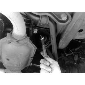
| Fig. 2: Loosen and remove the leading rod retainer
|