Previous Next

Ball Joint

REMOVAL & INSTALLATION

Justy

Fig. 1: Ball joint mounted to the steering knuckle and control arm — Justy

  1. Disconnect the negative battery cable.
  2. Raise and safely support the vehicle on jackstands.
  3. Remove the tire and wheel assembly.
  4. Remove the lower ball joint cotter pin and castle nut. Discard the cotter pin.
  5. Separate the ball joint stud from the lower control arm assembly.
  6. Remove the lower ball joint pinch bolt from the steering knuckle.
  7. Spread the ears on the steering knuckle and disconnect the ball joint from the steering knuckle.
  8. Installation is the reverse of removal. Secure the ball joint pinch bolt to 33 ft. lbs. (44 Nm).
  9. Tighen the ball joint castle nut to 29 ft. lbs. (39 Nm).
Sedan Coupe, Loyale, XT, Wagon and Brat

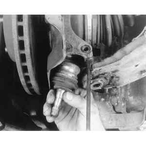
Fig. 2: Prying the steering knuckle to remove the ball joint assembly

  1. Disconnect the negative battery cable.
  2. Raise and safely support the vehicle on jackstands.
  3. Remove the front wheel and tire assembly.
  4. Remove the cotter pin from the lower ball joint castle nut, and discard.
  5. Loosen and remove the castle nut.
  6. Separate the ball joint stud from the lower control arm using a suitable tool.
  7. Remove the lower ball joint to steering knuckle pinch bolt.
  8. Using a suitable wedge, remove the lower ball joint from the steering knuckle.
  9. Installation is the reverse of removal. Secure the pinch bolt to 33 ft. lbs. (46 Nm) and the ball joint castle nut to 29 ft. lbs. (39 Nm). Install only a new cotter pin. If necessary to align the cotter pin tighten the nut. NEVER loosen the castle nut to align the cotter pin holes.
Legacy and Impreza

Fig. 3: Ball joint mounted to the steering knuckle and control arm — Legacy and Impreza

Fig. 4: Remove the cotter pin from the ball joint stud

Fig. 5: Loosen and remove the castle nut from the ball joint stud

Fig. 6: Using a puller to separate the ball joint from the control arm

Fig. 7: A prytool may be needed to raise the ball joint stud enough to clear the control arm

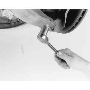
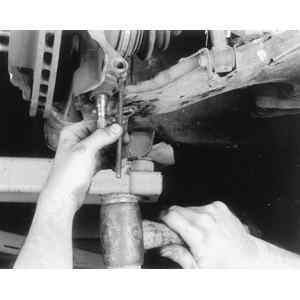
Fig. 8: Loosen the steering knuckle pinch bolt . . .

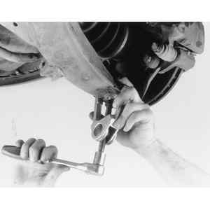
Fig. 9: . . . and remove from the mounting hole

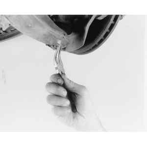
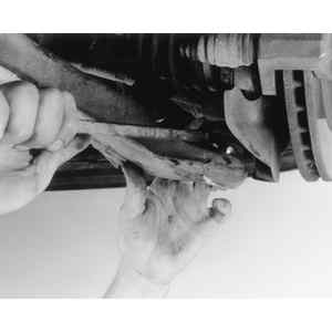
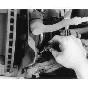
Fig. 10: Using a drift to wedge the steering knuckle mount enough . . .

Fig. 11: . . . to remove the ball joint

  1. Disconnect the negative battery cable.
  2. Raise and support the vehicle safely on jackstands.
  3. Remove the front wheel and tire assembly.
  4. Remove the ball joint castle nut cotter pin. Discard the cotter pin.
  5. Loosen and remove the castle nut.
  6. Using a suitable puller or prytool, disconnect the ball joint from the lower control arm assembly.
  7. Remove the bolt securing the ball joint to the steering knuckle. Use a suitable wedge to expand the steering knuckle connection point, and remove the ball joint.

    To install:

  8. Attach the ball joint to the steering knuckle, insert the bolt, and tighten to 36 ft. lbs. (49 Nm).
  9. Connect the ball joint to the lower control arm, and tighten the castle nut to 29 ft. lbs. (39 Nm). Then tighten the castle nut an additional 60°until the slot in the castle nut is aligned with the cotter pin hole in the ball joint. Install a new cotter pin.
  10. Install the wheel, lower the vehicle. Connect the negative battery cable.
SVX

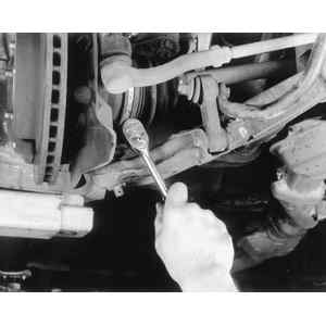
Fig. 12: Loosening the steering knuckle pinch bolt. The arrows indicate the ball joint-to-control arm retaining nut locations

  1. Raise and safely support the vehicle.
  2. Remove the tire and wheel assembly.
  3. Remove the ball joint-to-steering knuckle pinch bolt.
  4. Separate the ball joint from the steering knuckle assembly.
  5. Remove the three lower ball joint mounting nuts and remove the lower ball joint assembly.
  6. Install and secure all components in the reverse order of removal. Tighten the lower ball joint mounting nuts to 91 ft. lbs. (123 Nm). Tighten the pinch bolt and nut to 38 ft. lbs. (52 Nm).

Previous Next