When assembling the engine, give yourself a clean, dirt free work area. Next, clean every engine component again. The key to a good assembly is cleanliness.
Mount the engine block onto the engine stand and wash it one last time using water and detergent. Dishwashing detergent works well. While washing it, scrub the cylinder bores with a soft bristle brush and thoroughly clean all of the oil passages. Completely dry the engine and spray the entire assembly down with an anti-rust solution such as WD-40® or similar product. Take a clean lint-free rag and wipe up any excess anti-rust solution from the bores, bearing saddles, etc. Repeat the final cleaning process on the crankshaft. Replace any freeze or oil galley plugs which were removed during disassembly.
If the crankshaft main bearing journals have been refinished to a definite undersize, install the correct undersize bearing. Be sure that the bearing inserts and bearing bores are clean. Foreign material under inserts will distort bearing and cause failure.
Place the upper main bearing inserts in bores with tang in slot.
Note: The oil holes in the bearing inserts must be aligned with the oil holes in the cylinder block.
- Install the lower main bearing inserts on the bearing caps
- Clean the mating surfaces of block, bearing caps and rear main bearing cap
- Carefully lower the crankshaft into place. Be careful not to damage any bearing surfaces
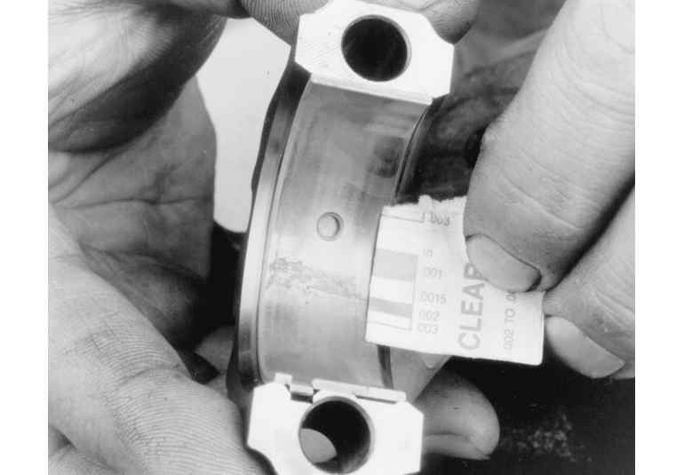
- Check the clearance of each main bearing by using the following procedure:
- Install the rear main seal.
Note: Be sure that main bearing caps are installed in original locations.
- After the bearings have been fitted, apply a light coat of engine oil to the crankshaft journals and bearings
- Install the rear main bearing cap
- Install all bearing caps except the thrust bearing cap
- Torque all bearing cap bolts to specification
- Install the thrust bearing cap with bolts finger-tight
- Pry the crankshaft forward against the thrust surface of upper half of bearing
- Hold the crankshaft forward and pry the thrust bearing cap to the rear. This aligns the thrust surfaces of both halves of the bearing
- Retain the forward pressure on the crankshaft and torque the cap bolts to specifications
- Measure the crankshaft end-play as follows:
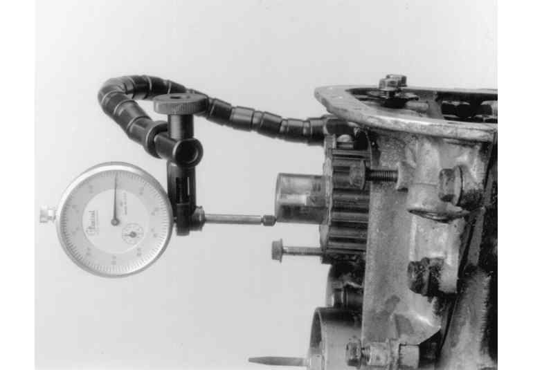
| Use a dial gauge to check crankshaft end-play

|
- Mount a dial gauge to the engine block and position the tip of the gauge to read from the crankshaft end.
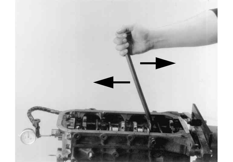
- Carefully pry the crankshaft toward the rear of the engine and hold it there while you zero the gauge.
| Carefully pry the crankshaft back and forth while reading the dial gauge for end-play
|
- Carefully pry the crankshaft toward the front of the engine and read the gauge
- Confirm that the reading is within specifications
- If not, install a new thrust bearing and repeat the procedure
- If the reading is still out of specifications with a new bearing, have a machine shop inspect the thrust surfaces of the crankshaft, and if possible, repair it
- Rotate the crankshaft to position the first rod journal (cylinder number one) to the bottom of its stroke
Before installing the piston/connecting rod assembly, oil the pistons, piston rings and the cylinder walls with light engine oil.
- Install connecting rod bolt protectors or rubber hose onto the connecting rod bolts/studs. Also perform the following:
- Select the proper ring set for the size cylinder bore
- Position the ring in the bore in which it is going to be used
- Push the ring down into the bore area where normal ring wear is not encountered
- Use the head of the piston to position the ring in the bore so that the ring is square with the cylinder wall. Use caution to avoid damage to the ring or cylinder bore
- Measure the gap between the ends of the ring with a feeler gauge. Ring gap in a worn cylinder is normally greater than specification. If the ring gap is greater than the specified limits, try an oversize ring set
| Checking the piston ring-to-ring groove side clearance using the ring and a feeler gauge
|
- Check the ring side clearance of the compression rings with a feeler gauge inserted between the ring and its lower land according to specification. The gauge should slide freely around the entire ring circumference without binding. Any wear that occurs will form a step at the inner portion of the lower land. If the lower lands have high steps, the piston should be replaced.
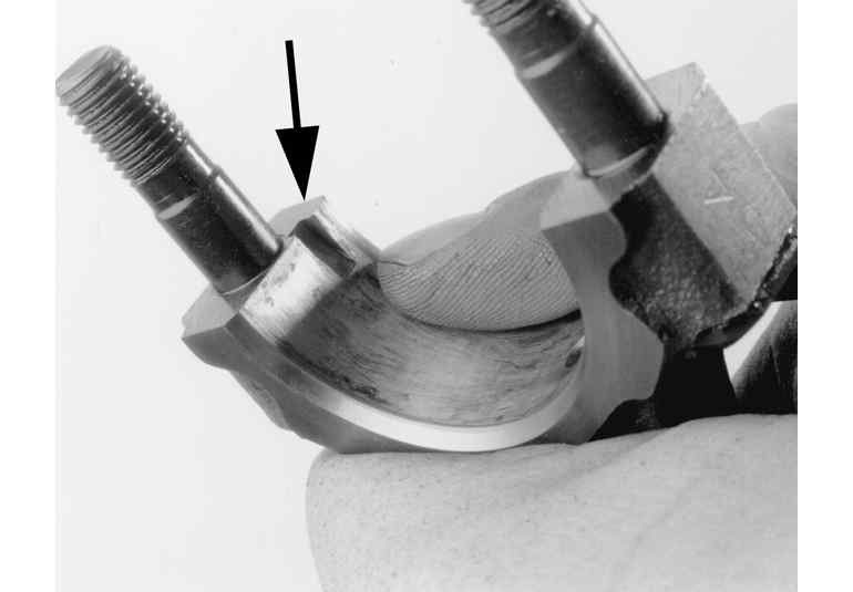
| The notch on the side of the bearing cap matches the tang on the bearing insert
|
- Unless new pistons are installed, be sure to install the pistons in the cylinders from which they were removed. The numbers on the connecting rod and bearing cap must be on the same side when installed in the cylinder bore. If a connecting rod is ever transposed from one engine or cylinder to another, new bearings should be fitted and the connecting rod should be numbered to correspond with the new cylinder number. The notch on the piston head goes toward the front of the engine.
- Install all rod bearing inserts into the rods and caps.
| Most rings are marked to show which side of the ring should face up when installed to the piston
|
- Install the rings on the pistons. Install the oil control ring first, then the second compression ring and finally the top compression ring. Use a piston ring expander tool to aid in installation and to help reduce the chance of breakage.
| Install the piston and rod assembly into the block using a ring compressor and the handle of a hammer
|
- Make sure the ring gaps are properly spaced around the circumference of the piston. Fit a piston ring compressor around the piston and slide the piston and connecting rod assembly down into the cylinder bore, pushing it in with the wooden hammer handle. Push the piston down until it is only slightly below the top of the cylinder bore. Guide the connecting rod onto the crankshaft bearing journal carefully, to avoid damaging the crankshaft.
- Check the bearing clearance of all the rod bearings, fitting them to the crankshaft bearing journals. Follow the procedure in the crankshaft installation above using Plastigage®.
- After the bearings have been fitted, apply a light coating of assembly oil to the journals and bearings.
- Turn the crankshaft until the appropriate bearing journal is at the bottom of its stroke, then push the piston assembly all the way down until the connecting rod bearing seats on the crankshaft journal. Be careful not to allow the bearing cap screws to strike the crankshaft bearing journals and damage them.
- After the piston and connecting rod assemblies have been installed, check the connecting rod side clearance on each crankshaft journal.
- Prime and install the oil pump and the oil pump intake tube.
- Install the assembled auxiliary/balance shaft(s)
- Install the camshaft
- Install the timing gears/chain assembly
- Install the lifters/followers into their bores
- Install the cylinder head(s) using new gaskets and torque the heads to engine specification
- Assemble the rest of the valve train (pushrods and rocker arms and/or shafts)
- Install the cylinder head(s) using new gaskets and torque the heads to engine specification
- Install the timing sprockets/gears and the belt/chain assemblies
- Install the timing cover(s) and oil pan. Refer to your notes and drawings made prior to disassembly and install all of the components that were removed. Install the engine in the vehicle.