Before disassembling the cylinder head, you may want to label some containers to hold the various parts, as some of them can be quite small (such as keepers) and easily lost. Also keeping yourself and the components organized will aid in assembly and reduce confusion. Number or otherwise mark the valves and corresponding combustion chambers so that their location will not be a mystery after you have disassembled the heads. This is especially important if there is not going to be any machine work performed on the components.
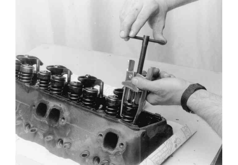
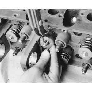
| When removing an OHV valve spring, use a compressor tool to relieve the tension from the retainer
|
Note: Due to engine varnish, the retainer may stick to the valve locks. A gentle tap with a hammer may help to break it loose.
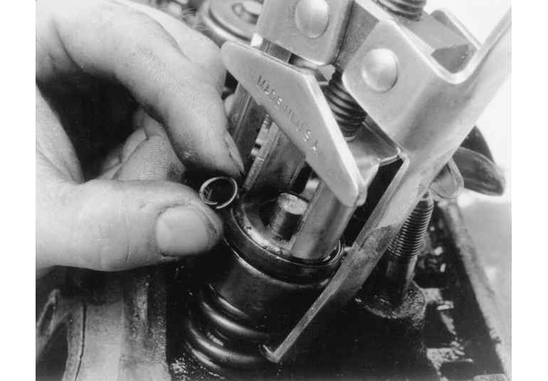
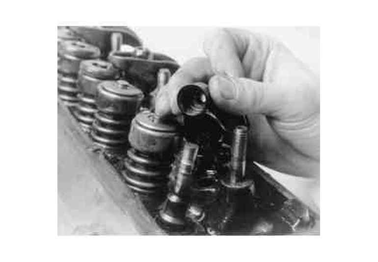
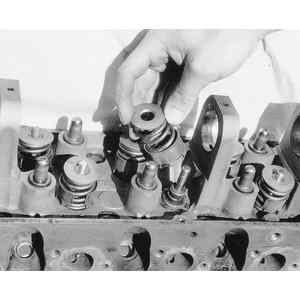
| A small magnet will help in removal of the valve locks
|
| Be careful not to lose the small valve locks (keepers)
|
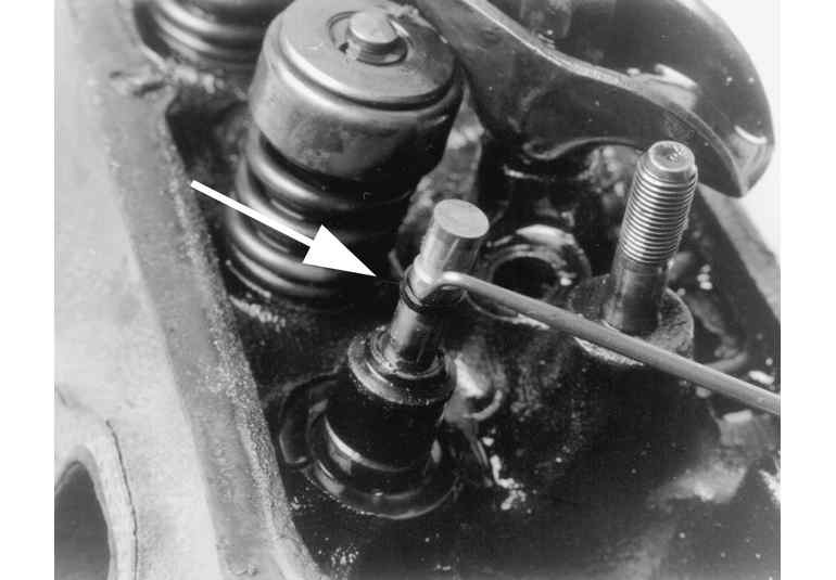
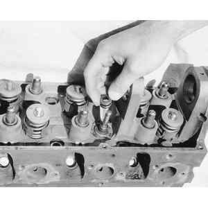
| Remove the valve seal from the valve stem-O-ring type seal shown
|
| Removing an umbrella/positive type seal
|
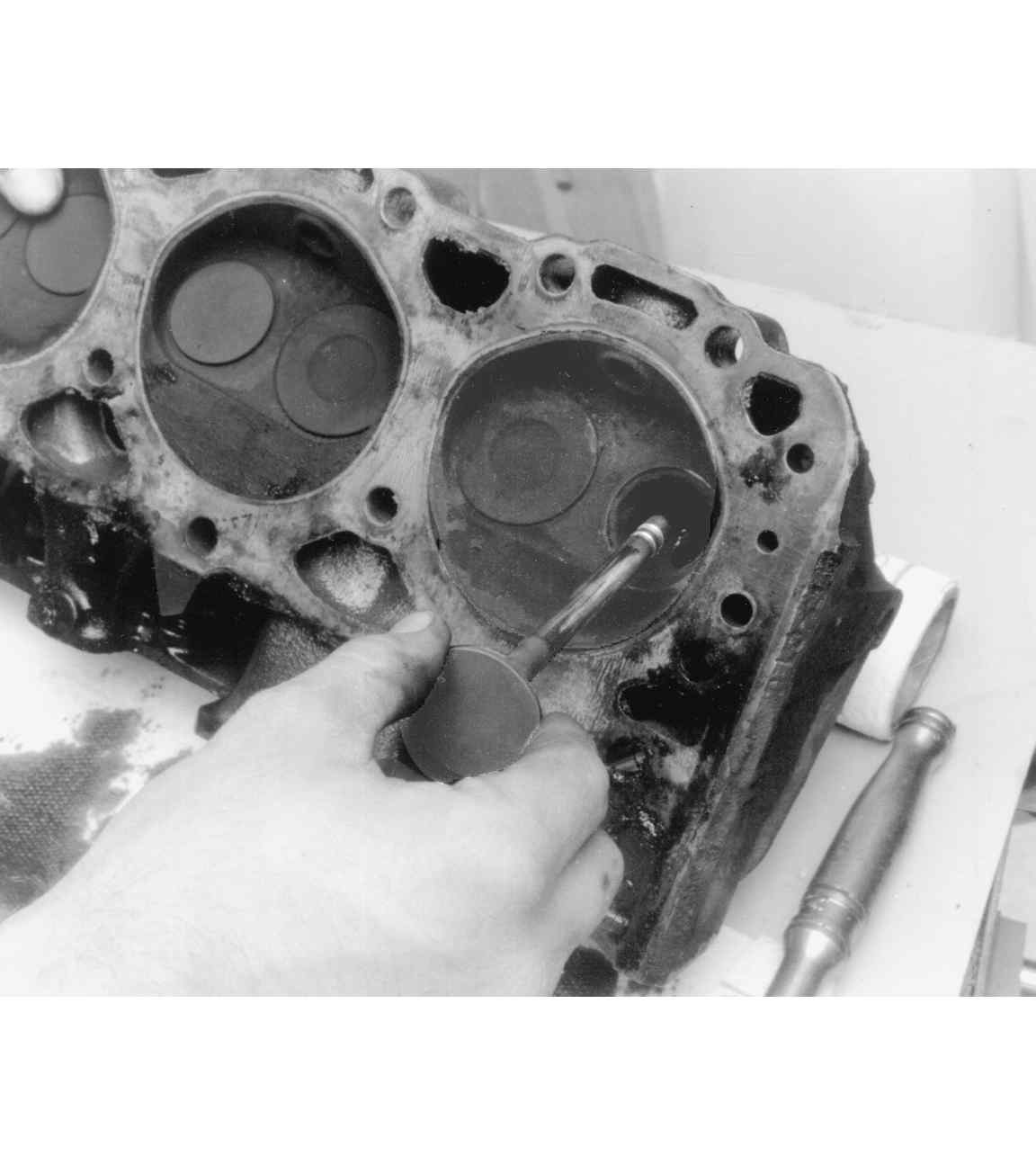
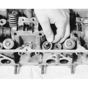
| Invert the cylinder head and withdraw the valve from the valve guide bore
|
Note: Cylinder heads that have many miles and/or have been abused may have mushroomed valve lock grooves and/or valve tips, making it difficult to remove valves. If this is so, use a metal file to carefully remove the high spots around the lock grooves and/or tip. File enough to make valve removal possible.
Whether it is a single or dual overhead camshaft cylinder head, the disassembly procedure is relatively unchanged. As always, pay attention and carefully labeling all parts. There will be a camshaft and several followers for the intake and exhaust valves. They must be labeled as such. In some cases, the components are identical and could be incorrectly installed. Do not mix them up! Determining which is which is very simple; the intake camshaft and components are on the same side of the head as where the intake manifold mounts to the cylinder head. Conversely, the exhaust camshaft and components are on the same side of the head as where the exhaust manifold mounts. You can easily stamp or scribe and I (intake) or E (exhaust) on the end of the camshafts to aid in installation. Make sure the markings are deep enough to withstand cleaning.
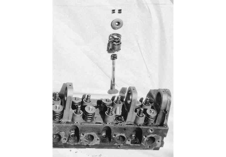
| Exploded view of a valve, seal, spring, retainer and locks from an OHC cylinder head
|
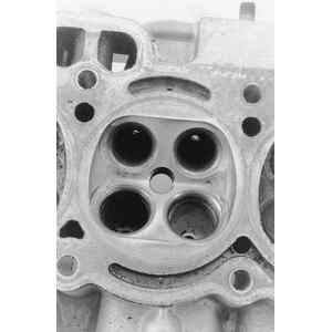
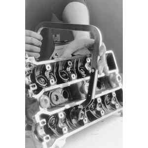
| Example of a multi-valve cylinder head. Note how it has 2 intake and 2 exhaust valve ports
|
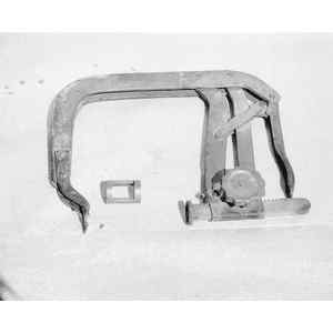
Most cylinder heads with cup type camshaft followers will have the valve spring, retainer and locks recessed within the followers bore. You will need a C-clamp style valve spring compressor tool, an OHC spring removal tool (or its equivalent) as well as a small magnet to disassemble the head.
| C-clamp type spring compressor and an OHC spring removal tool (center) for cup type followers
|
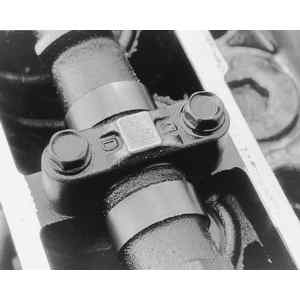
| Most cup type follower cylinder heads retain the camshaft using bolt-on bearing caps
|
Note: Position the cylinder head gasket surface facing you with the valve springs facing the opposite direction and the head lying horizontal.
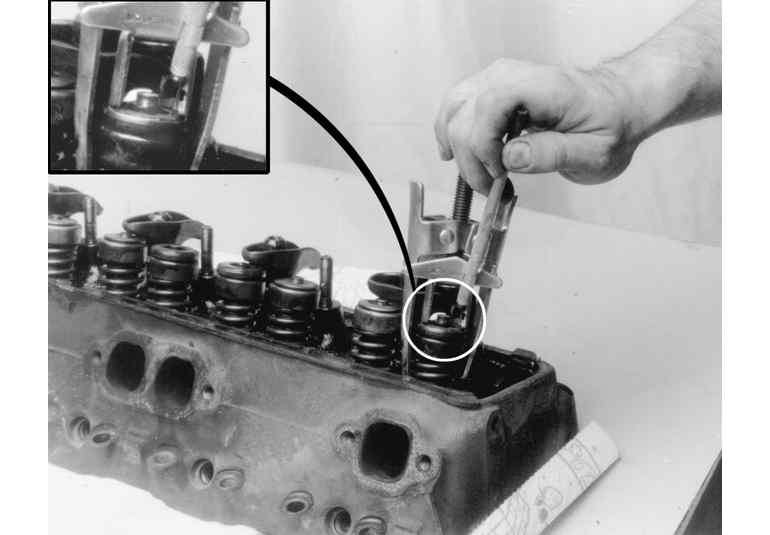
| Position the OHC spring tool in the follower bore, then compress the spring with a C-clamp type tool
|
Note: Check for burrs or high spots on the valve tip and valve lock area. Use a metal file to remove burrs before removing the valve from the head.
Note: Special valve seal removal tools are available. Regular or needle nose type pliers, if used with care, will work just as well. If using ordinary pliers, be sure not to damage the follower bore. The follower and its bore are machined to close tolerances and any damage to the bore will affect their relationship.
Most cylinder heads with rocker arm-type camshaft followers are easily disassembled using a standard valve spring compressor. Certain models may not have enough open space around the spring for the standard tool and may require you to use a C-clamp style compressor tool instead.
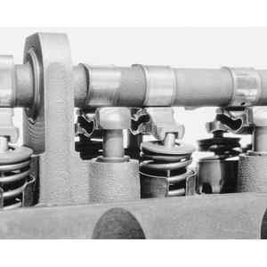
| Example of the shaft mounted rocker arms on some OHC heads
|
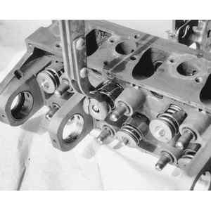
| Another example of the rocker arm type OHC head. This model uses a follower under the camshaft
|
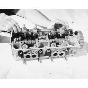
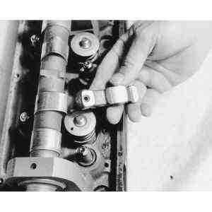
| Before the camshaft can be removed, all of the followers must first be removed . . .
|
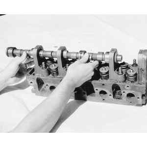
| . . . then the camshaft can be removed by sliding it out (shown), or unbolting a bearing cap (not shown)
|
| Compress the valve spring . . .
|
Note: Due to engine varnish, the retainer may stick to the valve locks. A gentle tap with a hammer may help to break it loose.
| . . . then remove the valve locks from the valve stem and spring retainer
|
| Remove the valve spring and retainer from the cylinder head
|
Note: If the seal is difficult to remove with the valve in place, try removing the valve first, then the seal.
| Remove the valve seal from the guide. Some gentle prying or pliers may help to remove stubborn seals
|
Note: Cylinder heads that have many miles and/or have been abused may have mushroomed valve lock grooves and/or valve tips, making it difficult to remove valves. If this is so, use a metal file to carefully remove the high spots around the lock grooves and/or tip. File enough to make valve removal possible.
| All aluminum and some cast iron heads will have these valve spring shims. Remove all of them as well
|