Electricity is based on the principle that electrons are attracted to protons. Electron movement can be created when the atomic structure of a material is forced to become imbalanced. Atoms are made up of an equal quantity of positively and negatively charged parts. The nucleus contains protons, with a positive charge, and neutrons with a neutral charge. The negative charge or electrons constantly orbit around the nucleus in valence rings.
If an electron were to be separated from an atom it would assume a net positive charge and become a position ion. On the other hand, if an element were to "acquire" an electron it would have a net negative charge and become a negative ion. If we were to store these positive and negative ions in a container we would have a power source, or battery.
Electricity is the flow of electrons from a greater potential (more electrons) to a lesser potential (less electrons). If a path were provided for the electrons from the negative ions to flow to the positive ions each ion could then maintain its balanced condition. The pressure that the electrons exert when returning to its source is called voltage. When voltage (V) is measured with a voltmeter, the value displayed represents the attractive force, or electromotive force available to get the atoms in balance again.
Amperage is a measure of the actually quantity of electrons that flow from the net negative charge to the net positive charge. This movement of electrons, or current, is what actually does the work in an electrical circuit. Current flow is measured in units of Amperes, or Amps (A). Amperage is a time-based unit. One Amp is equal to 6.28 x 1028 electrons moving past one point in one second. When an ammeter is connected in series with a circuit, the actual quantity of electrons that flow through the circuit are measured.
Resistance is an element�s ability to oppose current flow. The resistance of an element depends upon its atomic structure- specifically how many electrons are held in orbit in the outermost or valence ring. Up to eight electrons can occupy the valence ring of an atom. When fewer electrons are present in the valence ring there is more "room" for electrons to flow across the surface of an atom.
Electrically speaking, elements can be categorized as conductors, insulators and semi-conductors. Conductors are elements with between one and three electrons in their valence ring. Insulators are elements that contain between five and eight valence ring electrons. Semi-conductors are elements that contain four electrons in their valence ring.
Impedance is something that restricts flow. If you put a number of connections along an electrical circuit, each connection becomes a source of resistance slowing the flow of electricity to its final destination. A common analogy would be a coke bottle; if you turn a coke bottle upside down to empty its contents it takes a longer period of time to do so. There is resistance within the bottle to empty a large volume of fluid through a low volume orifice. Now, take the same bottle turned on its side so there is air space present at the mouth of the bottle while pouring out the fluid. The process takes less time due to low impedance (less resistance). The resistance we find in an electrical circuit is measured in Ohms. The resistance of a circuit varies depending on the amount and type of components used in the circuit. When an Ohmmeter is used to measure resistance. Current is applied to the component from a power source (battery) in the meter. The voltage that returns to the meter is converter to a resistive value.
The main factors which determine resistance are the material used, the size and cross section of the wire, the length of the wire and the temperature that these items operate. Some materials have more resistance than others. Those with high resistance are said to be insulators. Rubber materials (or rubber-like plastics) are some of the most common insulators used in vehicles as they have a very high resistance to electricity. Very low resistance materials are said to be conductors. Copper wire is among the best conductors. Most automotive wiring is made of copper. Silver is actually a superior conductor to copper and is used in some relay contacts, but its high cost prohibits its use as common wiring. Airbag systems commonly use gold plated terminal to ensure that current will readily flow through the system. Gold, while cost prohibitive, will not react to air and contaminants that can contribute to unwanted voltage drops.
Larger diameter wires provide more surface area for current flow. The larger the wire size being used, the less resistance the wire will have. Solid conductors provide less surface area when compared to stranded conductors. Stranded conductors have the capacity to carry greater currents when compared to solid conductors of the same gauge (size). This is because the individual strands of a stranded conductor contribute to greater surface area. This is why components which use large amounts of electricity have larger wires supplying current to them. All elements offer some degree of resistance. While copper wire, as an example, is a conductor, it too has a resistive value. For a given thickness of wire, the longer the wire, the greater the resistance. The shorter the wire, the less the resistance. When determining the proper wire for a circuit, both size (gauge) and length must be considered to design a circuit that can handle the current needed to provide enough power to the component being powered. With many materials, the higher the temperature, the greater the resistance (positive temperature coefficient). Some materials exhibit the opposite trait of lower resistance with higher temperatures (negative temperature coefficient). These principles are used in many of the sensors on the engine. As voltage flows through the wiring, these varying properties effect the overall performance of the electrical system, but the current is what actually does the work.
Many people have been taught electrical theory using an analogy with water. In a comparison with water flowing through a pipe, the electrons would be the water and the wire can be considered the pipe.
The flow of electricity can be measured much like the flow of water through a pipe. You can equate amperage, or electron flow to the volume of water flowing through a pipe. When relatively few electrons flow through a circuit, the amperage is low. When many electrons flow, the amperage is high. Electrical pressure is what forces electrons through a circuit just as pressure forces water through a pipe. Water pressure is measured in units such as pounds per square inch (PSI).
Resistance is what regulates current flow. Electrical resistance can be equated to a valve installed in the end of our water pipe. As the valve is closed, more resistance is added and the actual quantity of water that flows from the pipe is reduced. It is important to realize that the pressure before the valve is still the same as if the valve were not installed in the pipe.
There is a direct relationship between current, voltage and resistance. The relationship between current, voltage and resistance can be summed up by a statement known as Ohm's law.
Voltage (E) is equal to amperage (I) times resistance (R); or,
E=I x R
One volt will push one amp of current through one Ohm of resistance in one second�s time.
Ohm�s law can also be expressed as:
R=E/I or I=E/R
In each of these formulas, "E" is the voltage, "I" represents current (expressed in Amps) and "R" is resistance, expressed in Ohms. A majority of the electrical circuits in an automobile are designed to function at a voltage typically between 13.8 and 14.4 volts. When a stable voltage range is maintained, current flow is regulated by the resistance of the loads in any given circuit. The basic point to remember is that as the resistance of a circuit goes up, the amount of current that flows in the circuit will go down, so long as voltage remains the same.
The amount of work that can be performed in an electrical circuit is the product of pressure (voltage) forcing current through a circuit. This combination of amperage and voltage is power. The unit of power is the watt (W). The relationship between power, voltage and current in direct current (DC) circuits is expressed as:
Power (W) is equal to amperage (I) times voltage (E); or,
W=I x E
For as much as power can be an indication of how much work can be performed it is also a requirement. A certain amount of current has to be forced through a component in order for that component to function.
For any 12 volt, negative ground, electrical system, or circuit, to operate, the electricity must travel in a complete path. As a rule, electrons move from negative to positive. If you�ve ever seen slow motion footage of a lightning strike no doubt you�ve seen lightning originate in the clouds and move to the earth. The earth is actually the positive pole and the clouds are the negative. We consider conventional current to flow from positive to negative. In all actuality the negative electrons are moving to positive, jumping over the positive electrons that are being moved back to negative, thus completing the cycle of returning to the source. Simply put, current (power)flows from a source from the positive (+) terminal of the battery) and eventually returns back to to the source. Throughout this cycle, current flows through an endless maze of wiring, fuses, switches, and relays. If current is interrupted the component fed by that circuit ceases to function.
The easiest way to visualize a circuit is to think of connecting a 12-volt light bulb � with two wires attached � to the battery. One wire is attached to the negative terminal and the other to the positive terminal of the battery. This is a single load, series circuit. When both terminals are attached to the battery the circuit is complete and the light bulb would illuminate. Current follows a path from the battery through the light bulb and returns to the battery. On a typical electrical circuit this circuit would contain switches and/or controls and fuse protection.
| This example illustrates a simple circuit. When the switch is closed, power from the positive battery terminal flows through the fuse and the switch, and then through the light bulb. The light illuminates and the circuit is completed through the ground wire back to the negative battery terminal. In reality, the two ground points shown in the illustration are attached to the metal frame of the vehicle that completes the circuit back to the battery
|
Most automotive circuits differ from this simple example. Instead of having a "return wire" from the bulb to the battery, the current travels through the frame of the vehicle. Since the negative battery cable is attached to the frame (made of electrically conductive metal), the frame of the vehicle can serve as a ground wire to complete the circuit.
Three kinds or circuit configurations can be found in the automobile: the series circuit, the parallel circuit and the series-parallel circuit.
Series circuits have only one path for current to flow. Voltage is consumed as current flows through a series circuit. Current flow is consistent. Using a 12-volt circuit as an example voltage measured before the load would equal source voltage. Voltage measured after the load would be zero volts. An ammeter placed in series would read the same amperage if it were placed in the circuit before or after the load. There are relatively fewer series circuits used in automotive applications. They are commonly used to isolate circuits where higher current flow, such as a blower motor circuit.
Parallel circuits have multiple paths for current to flow. As additional paths are added to a parallel circuit, the amount of current flow increases because there are more paths for current to flow through. The branches of a parallel circuit have the same voltage available to them. One advantage of using parallel circuits is that the amount of wiring used to provide power to components is reduced. One single conductive path can provide the same power to multiple components.
Series parallel circuits incorporate a series portion and a parallel portion. Typically, a load is installed in the series portion to limit how much voltage is applied to the remaining parallel portion of the circuit. One example of a series-parallel circuit that can be found in automotive applications is the instrument panel illumination circuit. The dimmer, or rheostat, is a variable resistance installed in the series portion of the circuit. All of the instrument panel illumination lamps are wired in parallel. As the dimmer is rotated, voltage is regulated to the illumination lamps. The higher the resistance of the rheostat, the less voltage is allowed to flow through the illumination lamps. In turn, the brightness, of the lamps decreases.
There are two power sources in the automobile: the battery and the alternator. The battery supplies electrical power during starting or during periods when the current demand of the vehicle�s electrical system exceeds the output capacity of the alternator. The alternator supplies electrical current when the engine is running. Alternator�s contain a voltage regulator that works like an on/off switch. The regulator monitors the condition of the battery and when the battery drops below a specific voltage the regulator turns on the alternator to replenish the battery. Under high load situations the alternator will turn on to meet the increased demand.
In Most modern vehicles use a lead/acid electrochemical storage device called a battery. Twelve volt batteries consist of six 2.1 volt cells connected in series, so that the entire unit is capable of producing 12.6 volts of electrical pressure. Each cell consists of a series of positive and negative plates separated by insulators suspended in a weak solution of sulfuric acid and water. Typically a battery at full charge will contain 13.2 Volts. The negative and positive plates are made of dissimilar materials with unlike charges (positive and negative). The combination of these dissimilar materials with a sulfuric acid solution creates a chemical reaction within the battery. It is this reaction which produces current flow from the battery when its positive and negative terminals are connected to an electrical load.
A Battery�s Capacity To Store Electrons Is Based On Its Physical Construction. Batteries With A Greater Surface Area (More Plates) Have The Ability To Deliver Greater Amounts Of Power. This Storage Capacity Is Commonly Referred To As Cold Cranking Amps (CCA). Essentially It Describes How Many Amps Are Available At A Median Temperature Of 32-Degrees Fahrenheit. When Power Is Depleted From The Battery It Is Replaced By The Alternator, Restoring The Battery To Its Original Chemical State.
Maintaining a stable electrical environment is critical for engine management. This environment provides the means for electrical components to function properly as well provide a reference for the Engine Management System (EMS).
The alternating-current generator is the electrical systems primary source of power while the engine is running. The generator must produce enough power to meet the demands of the loads in the electrical system (e.g. ignition system, fuel pump, headlamps, blower motor, turn signal) and recharge the battery. It converts mechanical energy into alternating-current electricity, which is then rectified through diodes that alter it to direct current for the electrical system and for recharging the battery. The generator is belt driven.
There three basic parts of the automotive generator (alternator). They include the rotor, the stator and the rectifier. The rotor is made up of a single conductor wound into many turns. The stator is made up of three sets of windings. The wire that the stator is made up of is larger than the wiring used in the rotor. The rotor spins inside of the stator and does not physically touch it. As current flows through the rotor, it is induced into the stator. Regulating current through the rotor of the generator controls generator output. The greater the field current through the rotor, the greater the current induced into the stator. The induced current in the stator flows through a rectifier bridge to the battery because the battery is at a lower voltage potential than the stator.
The rectifier bridge splits the AC voltage inducted into the stator. The positive portion of the AC voltage flows through three of the diodes and on to the positive side of the battery. The negative portion of the AC voltage flows through the remaining diodes and on to the negative side of the battery.
Ground provides an area of lower potential so that current can flow through electrical circuits. Two types of grounds are used in automotive electric circuits. Direct ground components are grounded to the frame through their mounting points. All other components use some sort of ground wire which is attached to the frame or chassis of the vehicle. The electrical current runs through the chassis of the vehicle and returns to the battery through the ground (�) cable. If you look, you'll see that the battery ground cable connects between the battery and the frame or chassis of the vehicle.
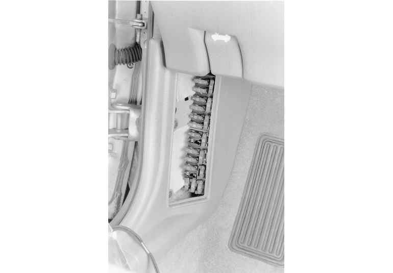
| Most vehicles use one or more fuse panels. This one is located on the driver�s side kick panel
|
It is possible for large surges of current to pass through the electrical system of your vehicle. If this surge of current were to reach the load in the circuit, this surge could burn it out or cause severe damage to the vehicle�s electrical system. It can overload the wiring, causing the harness to get hot and melt the insulation. To protect vehicle wiring, fuses, circuit breakers and/or fusible links are typically installed into the power supply wires throughout the electrical system. These items are nothing more than a built-in weak spot in the system. When an excessive amount of current flows through a circuit it causes an increase in heat throughout the wiring. Fuses and circuit breakers are designed as the weak link in the system and will disconnect the circuit to prevent damage to the components contained within that circuit. Components are equipped with connectors so they may be replaced in situations where they were damaged due to a power surge.
The following are descriptions as to how fuses and circuit breakers protect the electrical system:
CAUTION
Always replace fuses, circuit breakers and fusible links with identically rated components. Under no circumstances should a protection device of higher or lower amperage rating be substituted.
Switches are used in electrical circuits to control current flow. The most common use of relays and switches is to open and close circuits between the battery and various electrical loads in a circuit. loads are rated according to the amount of amperage they can handle. All of the current that the controlled load uses flows through a switch. Using a switch with an amperage rating lower than what the circuit is rated for could overload and cause damage to the components located on that circuit. Relays
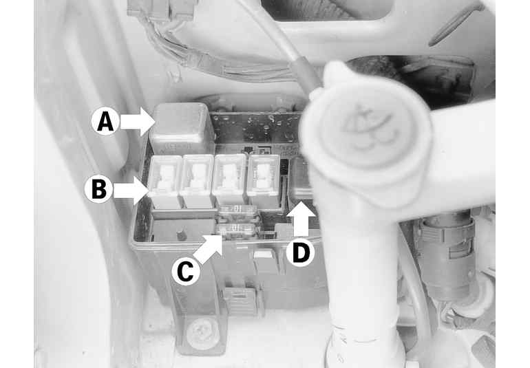
| The underhood fuse and relay panel contains fuses, relays, flashers and fusible links
|
Relays are used to control high-current loads with lower currents. Since these some loads require a large amount of current, the thickness of the wire in the circuit is also greater. If a switch were used to control the circuit, all of the current required to power the high-current load would have to pass through the switch. From a design standpoint, relays are used to limit current through switches and reduce the amount of heavy gauge wiring in the vehicle.
Relays are constructed of a set of switch contacts and a small electro-magnetic coil. When current flow through the coil a magnetic field is created. This field causes the contacts to touch, in turn completing the high-current circuit. Typically, relays are constructed so that the secondary contacts are open when the relay is de-energized (turned off). Circuits where relays are used include, but are not limited to, the horns, headlights, starter motor, electric fuel pump, blower motor and cooling fan motor.
| Relays are composed of a coil and a set of switch contacts. The large wires connect a high current power source to one side of the relay switch contacts and from the other side of the relay switch contacts to the load. The smaller wires connect a low current power source to the relay control coil and from the control coil to the control switch and then to ground.
|
Every electrical circuit must include a "load'' (something to consume voltage from the power source). Loads are resistances included in circuits to limit current flow. Loads are the components installed in circuits, such as headlights, wiper motors, door lock solenoids. Without a load, the battery would flow all of its energy through a circuit directly to ground. This is called a "dead-short to ground". The unchecked flow of electricity would cause a great amount of damage to the circuit by developing a tremendous amount of heat. Short circuits can develop sufficient heat to melt the insulation of surrounding wires, even reducing a multiple wire cable to a lump of plastic and copper.
Automotive wiring or circuit conductors can either be single stranded wire, multi-stranded wire. Where space is limited printed circuits can be used instead of traditional wiring. Single strand wire has a solid metal core and is usually used inside such components as alternators, motors, relays and other devices. Multi-strand wire has a core made of many small strands of wire twisted together to form a single conductor. Most wiring in an automotive electrical system is made up of multi-strand wire. Multi-stranded wire has more surface area when compared to solid-core wire and can carry more current. Automotive wiring is color coded on the insulator to identify individual circuits.
Printed circuits are constructed of a thin film of copper or other conductive material that is bonded to a non-conductive backing. Occasionally, the conductive material is sandwiched between two sheets of plastic for added protection. A complete printed circuit consisting of conductors, insulating material and connectors for lamps or other components is called a printed circuit board. Printed circuitry is used in place of conventional wiring in places such as the instrument cluster, computer modules and, in some cases, taillight assemblies.
The wire gauge number is an expression of the cross-section area of the conductor. . The most common system for expressing wire size is the American Wire Gauge (AWG) system. As gauge number increases, area decreases and the wire becomes smaller. An 18-gauge wire is smaller than a 4-gauge wire. In this instance, the higher the wire gauge, the smaller load it can carry, and the smaller the wire gauge the higher the load capability. Vehicles from countries that use the metric system will typically describe the wire size as its cross-sectional area in square millimeters (mm2). Simply put, the larger the wire, the greater the number. Gauge wire size refers to the size of the strands of the conductor, not the size of the complete wire with insulator. It is possible, therefore, to have two wires of the same gauge with different diameters because one may have thicker insulation than the other.
Since automotive electrical systems are vulnerable to changes in resistance, the selection of properly sized wire is critical when systems are repaired. A loose or corroded connection or a replacement wire that is too small for the circuit will add extra resistance in turn limiting current flow.
An average vehicle contains a great deal of wiring with hundreds of individual connections. To protect vehicle wiring from damage and to keep them organized, they are grouped into bundles enclosed in plastic conduit or taped together to form a wiring-harness. Harnesses route power and ground to different parts of the vehicle. Individual wires are color-coded to help identify circuits where sections are hidden from view.
It is essential to understand how a circuit works before trying to figure out why it doesn't. An electrical schematic shows the path of electrical current through a circuit. Schematics visually break down the entire electrical system into individual circuits for diagnosis and repair of vehicle wiring. In a schematic, usually no attempt is made to represent wiring and components as they physically appear on the vehicle; switches and other components are drawn to show current flow through them. Wiring schematics show the cavity and/or terminal locations in multi-pin connectors to help locate test points. The schematic shows the technician the components in a circuit, the pin locations at the ECM, and provides a diagnostic tool to isolate electrical faults within a circuit.
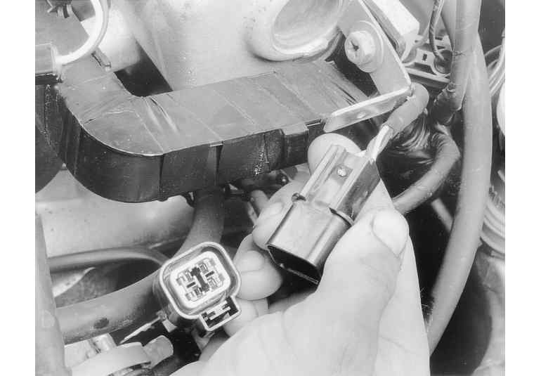
Three types of connectors are commonly used in automotive applications:
| Weatherproof connectors are most commonly used in the engine compartment or where the connector is exposed to the elements
|
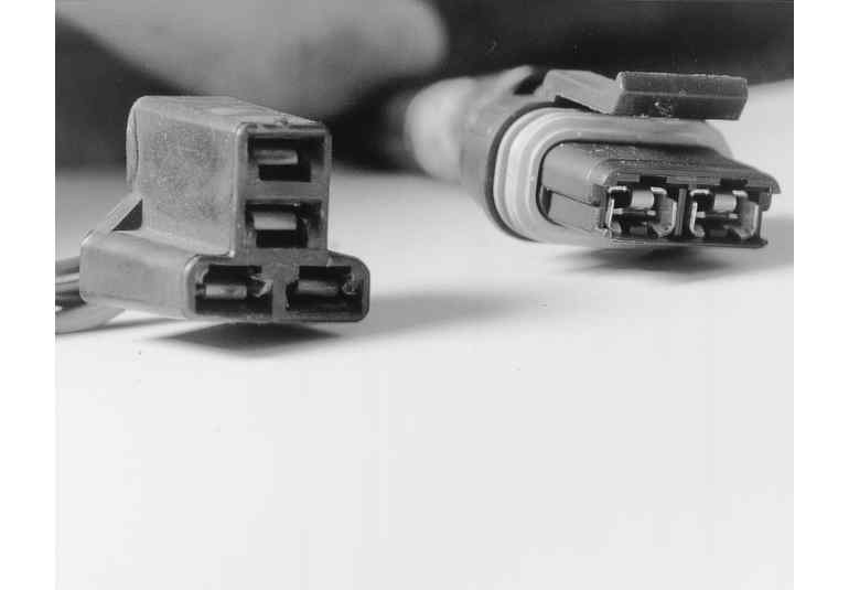
| Hard shell (left) and weatherproof (right) connectors have replaceable terminals
|
Use care when probing harness connections or replacing terminals, as it is possible to damage terminals or create a short circuit between terminals. If a short occurs between the wrong pair of terminals it is possible to damage vehicle wiring and components. Always use fused jumper wires between connectors for circuit checking and never probe through weatherproof seals or molded connectors.
Pinpointing the exact cause of electrical circuit requires the use of special test equipment. Here are descriptions of commonly used test equipment and a brief explanation of how they're used in the diagnosis of electrical problems. In addition to the information covered, the tool manufacturer's instruction booklet (provided with the test equipment) should be read and clearly understood before attempting any test procedures.
CAUTION
Always use a fused jumper made from the same gauge wire that�s used by that circuit. The fuse offers protects from accidentally creating shorts where a great deal of current would flow. A five amp fuse should be used. Never use jumper wires made from a thinner gauge wire than the circuit being tested. If the jumper wire is too small it may overheat and possibly melt. Never use jumpers to bypass high resistance loads in a circuit. Bypassing resistance, in effect, creates a short circuit. This can cause damage and fire. Jumper wires should only be used to bypass portions of a circuit�s wiring or switches.
Jumper wires are simple, yet extremely valuable pieces of test equipment. They are basically wires that are used to bypass sections of a circuit. Although jumper wires can be purchased, they can be fabricated from lengths of standard automotive wire and whatever type of connector (alligator clip, spade connector or pin connector) that is required for the particular application being tested. Insulated boots should cover the jumper wire terminals to prevent accidental grounding.
Jumper wires are used primarily to locate opens in electrical circuits. If an electrical component fails to operate, connect the jumper wire between the component and a good ground. If the component operates with the jumper installed in the ground circuit, the ground circuit is open. If the ground circuit is good, but the component does not operate, the circuit between the power feed and component may be open.
You can sometimes connect the jumper wire directly from the battery to the "hot" terminal of the component. Make sure the component operates on 12 volts. Some electrical components, such as sensors, are designed to operate on 5 volts. Running 12 volts directly to these components will cause damage.
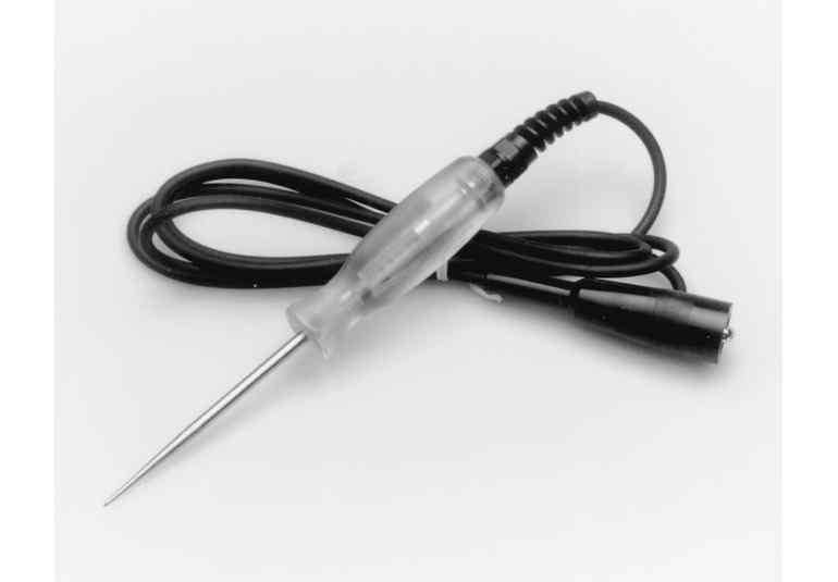
| A 12 volt test light is used to detect the presence of voltage in a circuit
|
Test lights are used to check for electrical current in circuits and components when a circuit is powered. Test lights are used to test for voltage and ground. To use a 12-volt test light, connect the ground clip to a good ground and probe wherever necessary with the pick. The test light will illuminate when voltage is detected. If the test light does not illuminate; there is an open circuit (no power). Move the test light in successive steps back toward the power source until the light in the handle illuminates. The open is between the test light and a point that was previously probed.
Test lights only indicate that power is available. This does not necessarily mean that adequate voltage (or any particular amount of voltage) is present; it only means that some voltage is present. Before using the test light, verify that it work by touching its ground clip to the negative battery terminal and probe the positive battery terminal to ensure that the light is operating.
WARNING
Do not use a test light to probe electronic ignition, spark plug or coil wires. Never use a pick-type test light to probe wiring on computer controlled systems unless specifically instructed. Any wire insulation that is pierced by the test light probe should be sealed after testing with liquid tape.
The self-powered test light is similar in design to the 12 volt test light, but contains a 1.5 volt battery in the handle. It is most often used in place of a Digital Volt- Ohm Meter (DVOM) to check for open circuits. The self-powered test light can also be used to perform continuity checks when power is isolated from the circuit.
The battery in a self-powered test light does not provide much current. A weak battery may not provide enough power to illuminate the test light even when a complete circuit is made (especially if the circuit has high resistance). Always make sure that the battery in the self-powered test light has a sufficient charge. To check the battery, remove the battery from the tester and connect to a DVOM to check the total voltage available. Replace the battery if the voltage is less than adequate.
NOTE: A self-powered test light should not be used on any computer controlled system or component. The small amount of power applied to the circuit or component from the test light is enough to damage many electronic automotive components.
Multimeters are an extremely useful tool for troubleshooting electrical problems. They can be purchased in either analog or digital form and have a price range to suit any budget. A multimeter is a voltmeter, ammeter and ohmmeter (along with other features) combined into one instrument. It is often used when testing solid state circuits because of its high input impedance (usually 10 Mega-Ohms or more). A brief description of the multimeter main test functions follows:
Voltmeter- This meter function is used to measure voltage at any point in a circuit, or to measure the voltage drop across any part of a circuit. Voltmeters usually have various scales and a selector switch to allow different voltage in various voltage ranges. The voltmeter has a positive and a negative lead. Note that the voltmeter's negative lead will always be black and that the positive will always be some color other than black (usually red).
Ohmmeter- this meter function is used to read resistance (measured in Ohms) of a circuit or component. Most ohmmeters will have a selector switch which permits the measurement of different ranges of resistance (usually the selector switch allows the multiplication of the meter reading by 10, 100, 1,000 and 10,000). Some ohmmeters are "auto-ranging" which means the meter itself will determine which scale to use.
Since the ohmmeter function uses an internal battery, the circuit should be isolated from any vehicle power sources when it is tested. When the ohmmeter is connected, current from the ohmmeter flows through the circuit or component being tested. Since the ohmmeter's internal resistance and voltage are known values, the amount of current flow through the meter depends on the resistance of the circuit or component being tested.
The ohmmeter can also be used to perform a continuity test for suspected open circuits. When using the meter for continuity checks, do not be concerned with the actual resistance reading. Zero resistance, or any Ohm reading, indicates continuity in the circuit. Infinite resistance indicates an open in the circuit. High resistance readings, where there should be none, indicate a circuit problem. Short circuits checks are made in the same manner as open circuit checks, except that the circuit must be isolated from both power and normal ground. Infinite resistance indicates no continuity, while zero resistance indicates a dead short.
WARNING
Never use an ohmmeter to check the resistance of a component or wire while there is voltage applied to the circuit.
Ammeter- This function is used to Measure the amount of current flowing through a circuit in units called Amperes or Amps. All circuits have a characteristic amount of amperes, called "current draw'' which can be measured using an ammeter. By referring to a specified current-draw rating, then measuring the amperes and comparing the two values, what is happening within the circuit can be used to diagnose the circuit.
Excessive current draw can blow fuses and drain the battery, while a reduced current draw can cause motors to run slowly, lights to dim and other components to not operate properly.
The ammeter is always connected in series with the circuit being tested. All of the current that flows through the circuit must also flow through the ammeter. The ammeter itself has very little resistance to current flow and typically will not affect circuit operation. The ammeter will measure current draw only when the circuit is closed and electricity is flowing.