Determining voltage available at the battery should be the first step in any electrical troubleshooting procedure, after a visual inspection. Many electrical problems, especially on computer controlled systems, can be caused by a low state of charge in the battery. Excessive corrosion at the battery cable terminals will inhibit proper charging and proper battery current flow.
- Ensure that the engine is not running and all electrical accessories are turned off
- Set the voltmeter selector switch to the 20V position (minimum)
- Connect the multi-meter negative lead to the battery's negative post or terminal and the positive lead to the battery's positive post or terminal.
- A fully charged battery will have 12.6 volts
- A battery voltage under 12.4 volts will require the battery to be charged before continuing any diagnosis
- When battery voltage is higher than 12.6 volts, the battery is holding a surface charge. The surface charge can be removed by turning on the headlights for 15 seconds and then turning them off. Allow the battery to rest for fifteen seconds and measure battery voltage again
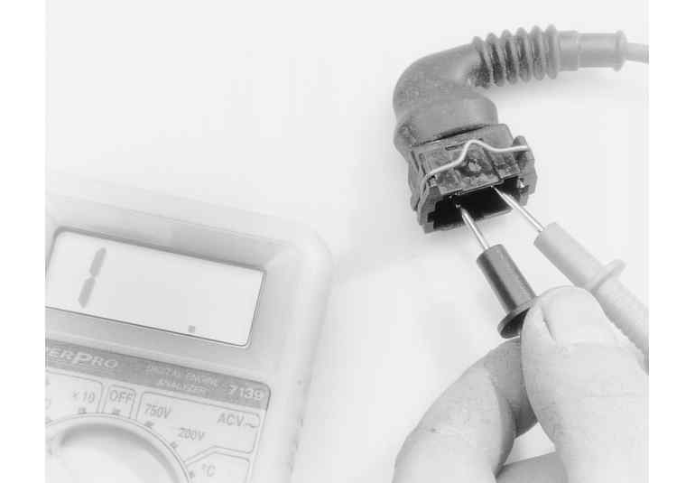
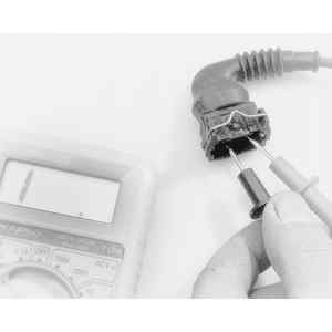
| The infinite reading on this multimeter indicates that the circuit is open
|
NOTE: This test already assumes the existence of an open in the circuit and it is used to help locate the open portion.
- Isolate the circuit from power and ground
- Connect the self-powered test light or ohmmeter ground clip to the ground of the circuit
- Probe sections of the circuit systematically
- If the light is out or there is infinite resistance, the open is between the probe and the circuit ground
- If the light is on or the meter shows continuity, the open is between the probe and the end of the circuit toward the power source
NOTE: Never use a self-powered test light to perform checks for opens or shorts when power is applied to the circuit. The test light can be damaged by outside power.
- Isolate the circuit from power and ground
- Connect the test light or ohmmeter ground clip to a good ground. Probe any easy-to-reach point in the circuit
- If the light comes on or there is continuity, there is a short somewhere in the circuit
- To isolate the short, probe a test point at either end of the isolated circuit
- The light should be on or the meter should indicate continuity
- Leave the test light probe engaged and sequentially open connectors or switches, remove parts, etc., until the light goes out or continuity is broken
- When the light goes out, the short is between the last two circuit components that were opened
When current flows through a load, the voltage after the load decreases. This voltage drop is due to the resistance of the load. Voltage drops also occur because of unwanted resistance created by corrosion at connectors and damaged portions of vehicle wiring. The maximum allowable voltage drop under load is critical.
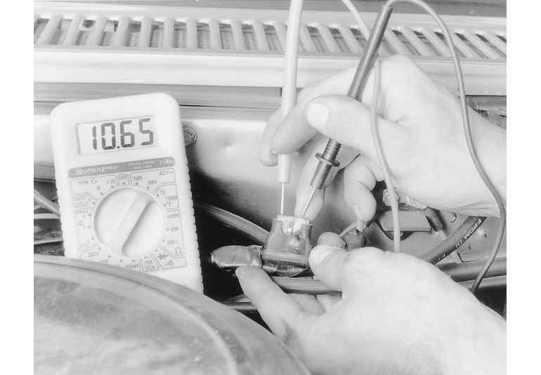
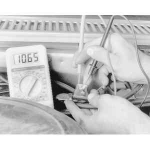
| This voltage drop test revealed high resistance (low voltage) in the circuit
|
NOTE: Voltage drops should be performed systematically through a circuit. Verify power portions of the circuit and then the ground portions. These steps outline performing voltage drop tests on the wiring that provides power to loads, not the loads themselves.
- Set the voltmeter selector switch to the 20V position
- Connect the negative lead of the multi-meter to the most negative portion of the circuit (closest to the load) of the portion of the circuit to be tested
- Connect the positive lead of the multi-meter to the most positive portion of the circuit (closest to the power source) of the portion of the circuit to be tested
- Operate the circuit and check the voltage displayed on the meter
- The voltage displayed is the voltage consumed through that portion of the circuit
- There should be little or no voltage drop in the circuit before or after the load in the circuit
- If a voltage drop exists, the wiring or connectors in the circuit are suspect. Diagnose and repair any cause of excessive resistance
- Repeat the test for section of wire in the circuit
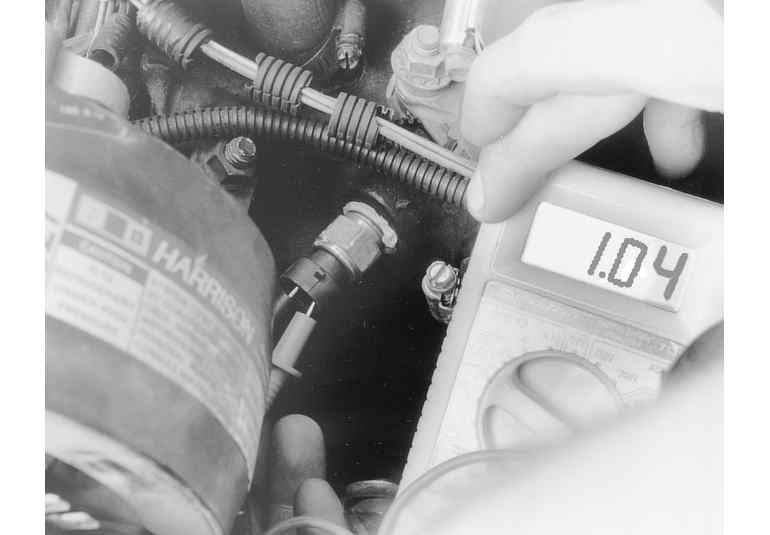
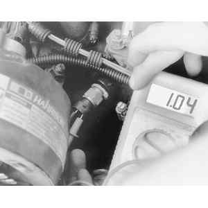
| Checking the resistance of a coolant temperature sensor with an ohmmeter. Reading is 1.04 kilohms
|
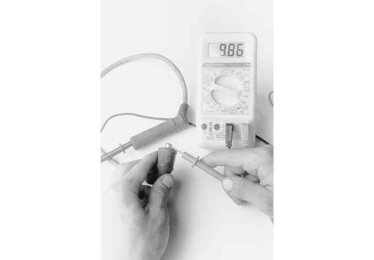
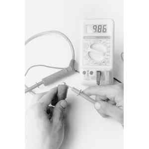
| Spark plug wires can be checked for excessive resistance using an ohmmeter
|
WARNING
Never use an ohmmeter with power applied to the circuit. The ohmmeter is designed to operate on its own power supply. The normal 12V electrical system voltage could damage the meter!
CAUTION
Ensure that the ignition key is OFF when disconnecting any components or the battery. The voltage spike and current that can flow though a circuit when a component or he battery is disconnected can damage sensitive electronic components, switch contacts and terminals.
- Isolate the circuit from the vehicle's power source
- Where necessary, also isolate at least one side of the circuit to be checked, in order to avoid reading parallel resistance. Parallel circuit resistance will always give a lower reading than the actual resistance of either of the branches
- Set the range selector to the proper scale for the circuit being
- If the resistance of the circuit is not known, start at a higher scale and incrementally scale down the meter to obtain the most accurate value
- Connect the meter leads to both sides of the circuit (wire or component)
- The value, displayed in Ohms, represents the resistance of that portion of the circuit.